Satellite observation method and system

A satellite observation and azimuth technology, applied in radio wave measurement systems, measurement devices, radio wave reflection/reradiation, etc., can solve the problems of large observation width and high observation cost

Active Publication Date: 2016-11-09
INST OF ELECTRONICS CHINESE ACAD OF SCI
View PDF5 Cites 6 Cited by
  • Summary
  • Abstract
  • Description
  • Claims
  • Application Information

AI Technical Summary

Problems solved by technology

However, limited by blur, the quality factor of SAR conventional imaging modes (strip mode, scanning mode, etc.) is about 10,000. In the case of a fixed quality factor, it is difficult to obtain a large observation width while obtaining high resolution. , resulting in the need for more SARs to be imaged simultaneously when observing the ocean, and the observation cost is higher

Method used


Image

  • Satellite observation method and system
  • Satellite observation method and system
  • Satellite observation method and system

Examples


Embodiment Construction

[0035] The following will clearly and completely describe the technical solutions in the embodiments of the present invention with reference to the drawings in the embodiments of the present invention.

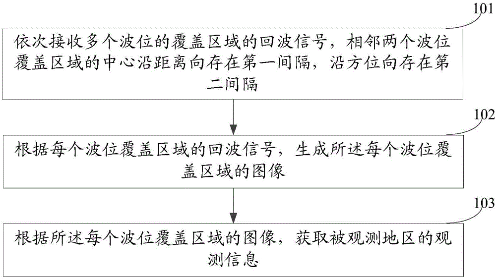
[0036] An embodiment of the present invention provides a satellite observation method, which is applied to SAR and can be used to observe oceans. Such as figure 1 As shown, the method includes:

[0037] Step 101 , receiving echo signals of coverage areas of multiple wave positions in sequence, where there is a first interval along the distance direction and a second interval along the azimuth direction between the centers of two adjacent wave position coverage areas.

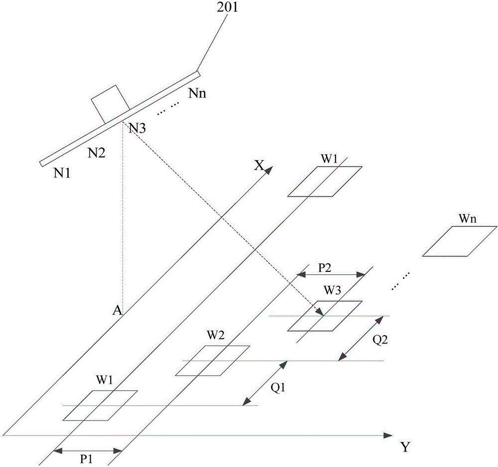
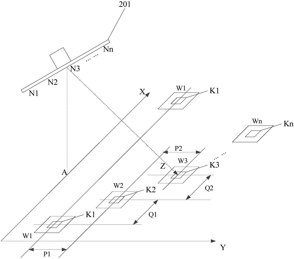
[0038] For example, multiple wave positions can be set on the spaceborne SAR first. The wave speed, launch time, beam center pointing, synthetic aperture and other parameters of each wave position are different, so the coverage area of ​​each wave position is also different. Specifically, such as figure 2 As...


PUM


Abstract

The embodiments of the invention disclose a satellite observation method. The method comprises the following steps: successively receiving echo signals of coverage areas of multiple wave positions, wherein a first interval exists along a distance direction and a second interval exits along an orientation direction between two adjacent wave position coverage areas; according to the echo signals of each wave position coverage area, generating images of each wave position coverage area; and according to the images of each wave position coverage area, obtaining observation information of an observed region. Furthermore, the embodiments of the invention disclose a satellite observation system.

Description

technical field [0001] The invention relates to ocean observation technology in the field of radar monitoring, in particular to a satellite observation method and system. Background technique [0002] With the development of microwave technology, the technology of imaging detection objects through microwave has been widely used, especially with the carrying of Synthetic Aperture Radar (SAR) on satellites, it is possible to observe the ground through satellites. [0003] In the prior art, when observing the ground through satellites, the SAR can first transmit microwaves to the ground. After the microwaves reach the ground, they are reflected by the ground to form an echo signal, and the SAR can receive the echo signal. Imaging is then performed based on the echo signal to obtain images of the ground. If the imaging effect is not good, it is difficult to achieve the purpose of observation, especially for the observation of the ocean, which requires long-term imaging with a h...

Claims


Application Information

Patent Timeline
Patent Type & Authority Applications(China)
IPC IPC(8): G01S13/90
CPCG01S13/90G01S13/9027
Inventor 孙吉利禹卫东郑明洁宋红军
Owner INST OF ELECTRONICS CHINESE ACAD OF SCI
Why Eureka
Try Eureka