Eureka AIR delivers breakthrough ideas for toughest innovation challenges, trusted by R&D personnel around the world.

A method for photolithography process optimization

An optimization method and technology of lithography process, applied in the direction of photoplate-making process of pattern surface, optics, and originals for photomechanical processing, etc., can solve the problems of expensive software and limited predictive ability, and achieve shortened processing time, cost reduction effect

Active Publication Date: 2019-11-22
SHANGHAI HUALI INTEGRATED CIRCUTE MFG CO LTD
View PDF2 Cites 0 Cited by
  • Summary
  • Abstract
  • Description
  • Claims
  • Application Information

AI Technical Summary

Problems solved by technology

However, given that different patterns, different sizes of the same pattern, and different intervals have different sensitivities to changes in lithography process parameters, it is difficult to fully reflect the pros and cons of each parameter selection with fewer data points, and its predictive ability is also limited. relatively limited
Also, such software is expensive

Method used


Image

  • A method for photolithography process optimization
  • A method for photolithography process optimization
  • A method for photolithography process optimization

Examples


Embodiment Construction

[0026] In order to make the content of the present invention clearer and easier to understand, the content of the present invention will be further described below in conjunction with the accompanying drawings. Of course, the present invention is not limited to this specific embodiment, and general replacements known to those skilled in the art are also covered within the protection scope of the present invention.

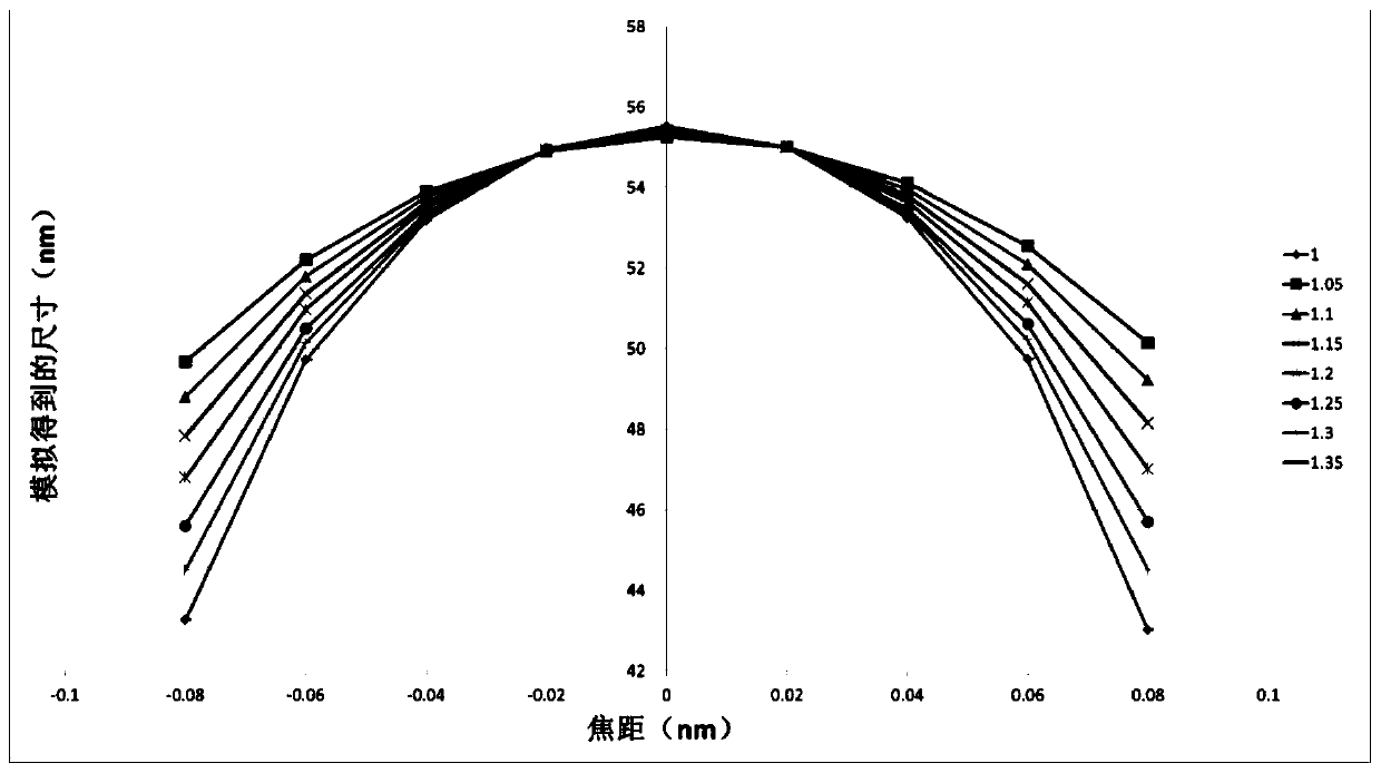
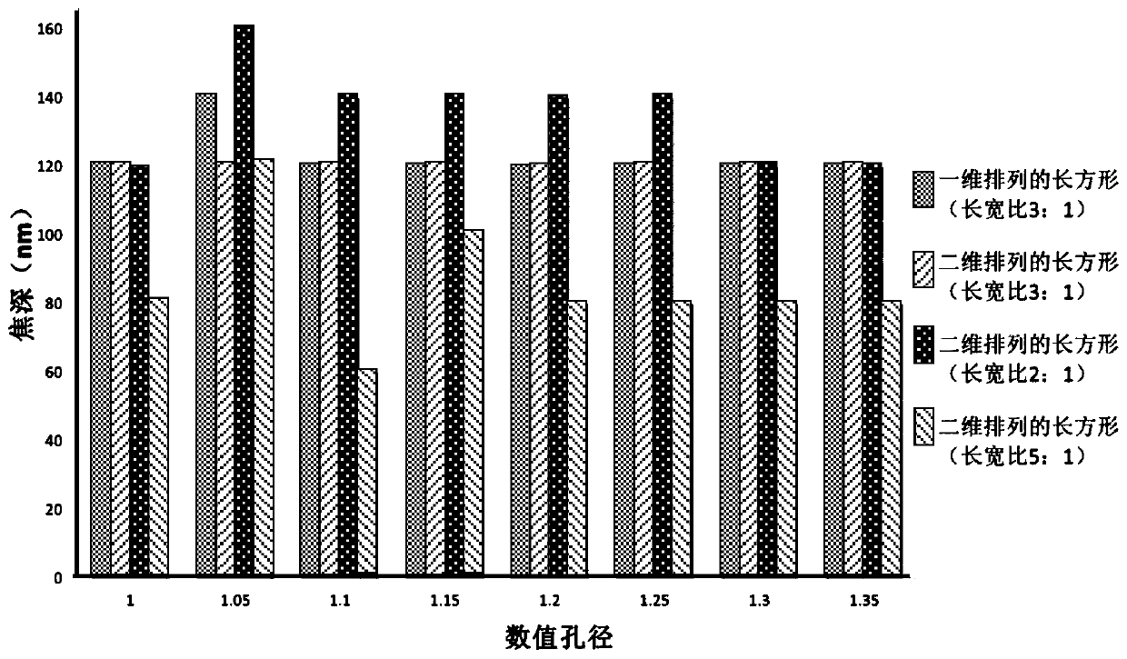
[0027] The following is attached Figure 1-4 The present invention will be described in further detail with specific examples. It should be noted that the drawings are all in a very simplified form, using imprecise scales, and are only used to facilitate and clearly achieve the purpose of assisting in describing the present embodiment.

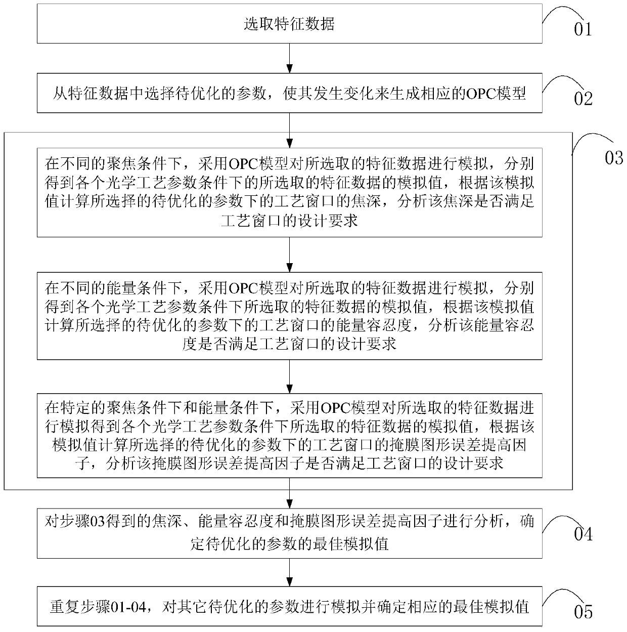
[0028] see figure 1 , the photolithography process optimization method of this embodiment, including:

[0029] Step 01: Select feature data;

[0030] Specifically, the feature data includes: the size, shape and distance between...


PUM


Abstract

The invention provides a photolithographic process optimization method which comprises the following steps: selecting feature data; selecting a parameter to be optimized from the feature data to generate a corresponding OPC model; under different focusing conditions, under different energy conditions and under a circumstance that the focusing conditions and the energy conditions are constant, adopting the OPC model to conduct simulation on the selected feature data respectively to obtain the simulated values of the selected feature data under various optical process parameter conditions respectively, calculating the focal depth, the energy tolerance and the mask pattern error enhancement factor of a process window adopting the selected parameter to be optimized according to the simulated values respectively, and analyzing whether the focal depth, the energy tolerance and the mask pattern error enhancement factor meet the design requirements of the process window or not; determining the optimal simulated value of the parameter to be optimized; repeating the processes to conduct simulation on other parameters to be optimized, and determining the corresponding optimal simulated value.

Description

technical field [0001] The invention relates to the technical field of integrated circuits, in particular to a photolithography process optimization method. Background technique [0002] The lithography process parameters affect the lithography process quality, in order to improve the lithography process quality can be realized by optimizing the lithography process parameters. Usually, the important parameters of the lithography process include: depth of focus (DOF), energy tolerance (EL), mask pattern error enhancement factor (Mask error enhancement factor, MEEF), numerical aperture (NA), light source radius (Sigma) Wait. Among them, the depth of focus (DOF) refers to the distance that the focal plane (focus) is allowed to move along the optical axis of the lens under the premise of maintaining a relatively clear image. The DOF under the process window refers to the allowable focal length change distance when the size changes within a certain specification. Energy tolera...

Claims


Application Information

Patent Timeline
Patent Type & Authority Patents(China)
IPC IPC(8): G03F1/36
CPCG03F1/36
Inventor 吴维维毛智彪陈权于世瑞
Owner SHANGHAI HUALI INTEGRATED CIRCUTE MFG CO LTD
Why Eureka
Eureka Blog
Learn More