Cutting device

A technology for cutting devices and workpieces, applied in electrical components, semiconductor/solid-state device manufacturing, circuits, etc., can solve the problems of high manufacturing costs, large-scale, complex structures, etc., and achieve the effect of reducing the number of parts and costs.

Active Publication Date: 2016-11-09
DISCO CORP
View PDF5 Cites 12 Cited by
  • Summary
  • Abstract
  • Description
  • Claims
  • Application Information

AI Technical Summary

Problems solved by technology

[0005] However, the above-mentioned cutting device has the following problems. In particular, a plurality of mechanisms for conveying the workpiece are required, the overall structure of the device is complicated and enlarged, and the number of parts is large, which increases the manufacturing cost.

Method used


Image

  • Cutting device
  • Cutting device
  • Cutting device

Examples


Embodiment Construction

[0052] Hereinafter, preferred embodiments of the cutting device according to the present invention will be described in detail with reference to the drawings.

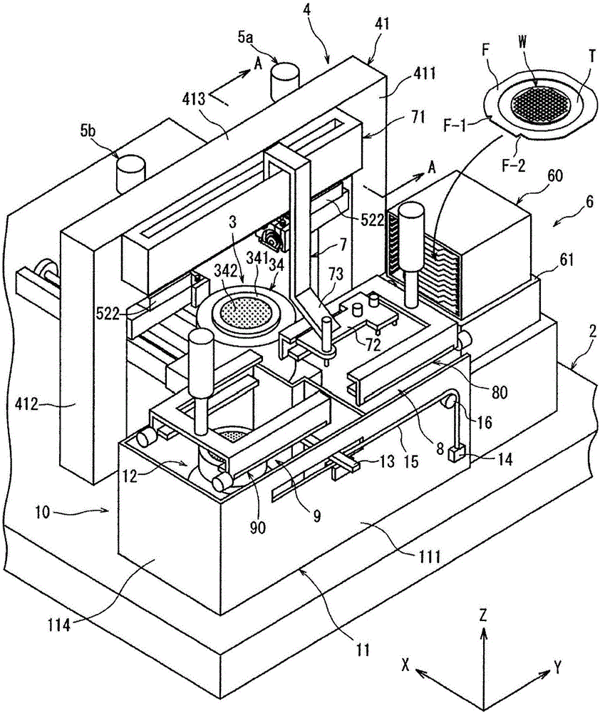
[0053] figure 1 A perspective view of an embodiment of a cutting device constructed in accordance with the present invention is shown in .

[0054] The cutting device of the illustrated embodiment includes: a stationary base 2; a holding table mechanism 3 arranged on the stationary base 2 to hold a workpiece; Cutting mechanism 4 for cutting workpieces.

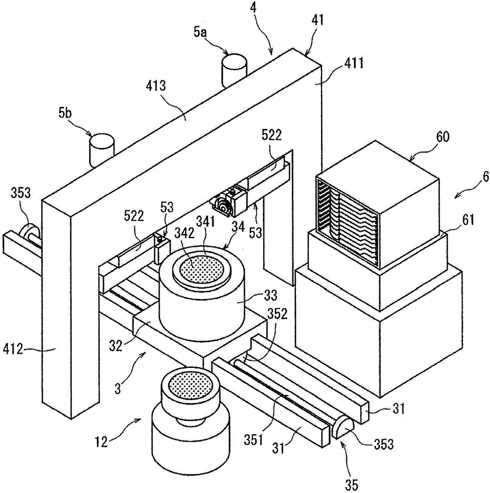
[0055] Hold the bench body 3 as figure 2 As shown, there are: two X-axis guide rails 31, 31, which are arranged on the stationary base 2 along the processing feed direction (X-axis direction) shown by arrow X; the movable base 32, which can slide The two X-axis guide rails 31, 31 are arranged in a manner; the holding table 34 for holding the workpiece is rotatably supported by a cylindrical support member 33, and the support member 33 is arranged on On the mobile ...


PUM


Abstract

The invention provides a cutting device which has the advantages that the overall structure of the device is simple and miniaturized; and the quantity of components is reduced, so that the manufacture cost is reduced. The cutting device comprises a processing feeding mechanism, a moving-out/moving-in mechanism, a holding component, a pair of limiting pins, a carrying and moving component, a temporary placement mechanism, an openable component and a lifting component, wherein the processing feeding mechanism comprises an X-axis guide rail, and the X-axis guide rail can ensure that a working table can be supported to move between a processed object assembly and disassembly area equipped with the temporary placement mechanism and a processing area equipped with a cutting mechanism in the X-axis direction; the moving-out/moving-in mechanism comprises a supporting base table; the holding component is disposed on the supporting base table and used to hold a processed object stored in a box; the pair of limiting pins limit the processed object at a stipulated position; the carrying and moving component enables the supporting base table to move in the Y-axis direction; the temporary placement mechanism comprises a pair of supporting rails, the supporting rails constitute a bottom part and a side part which extend in the Y-axis direction and support two side parts of the processed object, and the bottom part is openable; the openable component is used to open and close the bottom part of the pair of supporting rails; and the lifting component is used to move the pair of supporting rails up and down.

Description

technical field [0001] The present invention relates to a cutting device for cutting workpieces such as semiconductor wafers. Background technique [0002] In the manufacturing process of a semiconductor device, a plurality of regions are divided by dividing lines arranged in a grid on the front surface of a substantially disk-shaped semiconductor wafer, and devices such as ICs and LSIs are formed in the divided regions. Then, the individual semiconductor devices are manufactured by cutting the semiconductor wafer along the planned dividing lines to divide the regions where the devices are formed. [0003] A cutting device for cutting a workpiece such as a semiconductor wafer along a planned dividing line includes: a cassette mounting member that mounts a cassette containing a plurality of workpieces; and a carry-out / carry-in member that is placed on the cassette The box on which the component is placed carries out and carries in the processed object; the temporary storage ...

Claims


Application Information

Patent Timeline
Patent Type & Authority Applications(China)
IPC IPC(8): H01L21/78
CPCH01L21/78H01L21/67742H01L21/6773H01L21/67772H01L21/67739H01L21/67715H01L21/67712H01L21/67051
Inventor 大河原聪八木原惇寺师健太郎赤濑胜彦松冈伸太郎田中万平
Owner DISCO CORP
Why Eureka
Try Eureka