Electric equipment maintenance test grounding mechanical locking device

A technology of mechanical locking and power equipment, applied in the direction of substation grounding layout, switchgear, electrical components, etc., can solve the problem of long connection distance of grounding wires, out of sight range, non-compliance with maintenance test grounding controllable, under control, under control and other issues to achieve the effect of compact structure, preventing loosening, preventing accidental touch or misoperation

Pending Publication Date: 2016-11-09
成都立威讯科技有限公司
View PDF0 Cites 4 Cited by
  • Summary
  • Abstract
  • Description
  • Claims
  • Application Information

AI Technical Summary

Problems solved by technology

The grounding state in the traditional maintenance test does not meet the test requirements of the current substation. For example, the existing 10 kV and 35 kV switchgears use fully enclosed switch trolleys and the grounding bar is located at the back of the switchgear. The connection of the grounding wire The distance is long and not within the line of sight, which does not conform to the principle of controllable, controlled and controlled grounding for maintenance tests

Method used


Image

  • Electric equipment maintenance test grounding mechanical locking device
  • Electric equipment maintenance test grounding mechanical locking device
  • Electric equipment maintenance test grounding mechanical locking device

Examples


Embodiment 1

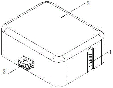
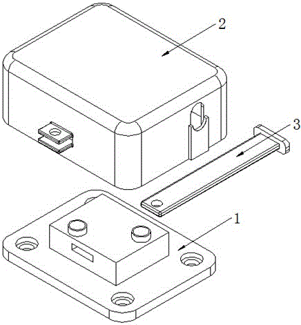
[0034] A grounding mechanical locking device for power equipment maintenance test in this embodiment, such as figure 1 , figure 2 As shown, it is mainly realized through the following technical solutions: a grounding mechanical locking device for power equipment maintenance and testing, including a grounding support 1 fixed on the grounding flat iron of the substation, an insulating protective shell 2 and a lock with a lock hole 31 Strip 3, the insulating protective shell 2 is covered above the grounding support 1 and is fixedly connected to the grounding support 1 through the locking bar 3; the grounding support 1 is provided with a ground threaded hole 11 for fixing the ground wire connector and connecting Slot 12; the insulating protective shell 2 is provided with a lock 21, a lock bar channel 22 and a grounding wire channel 23, and the lock bar 21 is located at the opening end of the lock bar channel 22; the lock bar 3 passes through the connecting groove 12, the lock bar...

Embodiment 2

[0036] This embodiment is further optimized on the basis of the above-mentioned embodiments. Further, the connecting groove 12 is a through groove that runs through the grounding support 1, and the locking strip channels 22 are correspondingly arranged at both ends of the connecting groove 12, and the locking strips 3 are respectively penetrated. Connect the slot 12 and the locking bar channel 22 . Other parts of this embodiment are the same as those of the foregoing embodiments, so details are not repeated here.

Embodiment 3

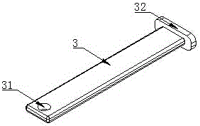
[0038] This embodiment is further optimized on the basis of the above embodiments, further, as image 3 As shown, the lock bar 3 is generally in the shape of a slat, with a positioning plate 32 disposed at one end and at least one lock hole 31 disposed at the other end. Other parts of this embodiment are the same as those of the foregoing embodiments, so details are not repeated here.


PUM


Abstract

The invention discloses a grounding mechanical locking device for the maintenance test of electric equipment, which comprises a grounding support fixed on a grounding flat iron of a substation, an insulating protective shell and a locking strip provided with a lock hole, and the insulating protective shell is covered on the grounding support The upper part is fixedly connected with the grounding support through the locking bar; the grounding support is provided with a ground threaded hole and a connecting groove for fixing the grounding wire connector; the insulating protective shell is provided with a lock, a locking bar channel and a grounding wire The lock is located at the opening end of the lock bar channel; the lock bar respectively passes through the connecting groove and the lock bar channel and connects the lock buckle and the lock hole correspondingly. Effectively prevent grounding wires from loosening and grounding devices from being misoperated, improve the accuracy of experimental data, and ensure personal and property safety.

Description

technical field [0001] The invention relates to the field of power equipment locking devices, in particular to a grounding mechanical locking device for power equipment maintenance tests. Background technique [0002] The rapid development of smart grid puts forward higher requirements for the safety of maintenance tests. The grounding state in the traditional maintenance test does not meet the test requirements of the current substation. For example, the existing 10 kV and 35 kV switchgears use fully enclosed switch trolleys and the grounding bar is located at the back of the switchgear. The connection of the grounding wire The distance is long and not within the line of sight, which does not conform to the principle of controllable, controlled and controlled grounding for maintenance tests. On the other hand, live tests such as cable fault inspection and arrester resistance test are becoming more and more common, and such live tests are more dependent on reliable groundin...

Claims


Application Information

Patent Timeline
Patent Type & Authority Applications(China)
IPC IPC(8): H02B3/00H02B5/01
CPCH02B3/00H02B5/01
Inventor 杨素贤
Owner 成都立威讯科技有限公司
Why Eureka
Try Eureka