
Flow direction changing controller and backwash pre-filter

A pre-filter and fluid direction technology, which is applied to fixed filter elements, filter separation, separation methods, etc., can solve problems such as difficult cleaning and inconvenient cleaning of impurities, and achieve fast operation, saving installation, and thorough cleaning Effect

Active Publication Date: 2016-11-16
杭州甲质科技有限公司
View PDF7 Cites 2 Cited by
  • Summary
  • Abstract
  • Description
  • Claims
  • Application Information

AI Technical Summary

Problems solved by technology

[0004] In order to overcome the inconvenient and difficult cleaning problems of impurities on the filter element in the existing pre-filter, the present invention provides a fluid direction conversion control and a backwash pre-filter

Method used


Image

  • Flow direction changing controller and backwash pre-filter
  • Flow direction changing controller and backwash pre-filter
  • Flow direction changing controller and backwash pre-filter

Examples


Embodiment 1

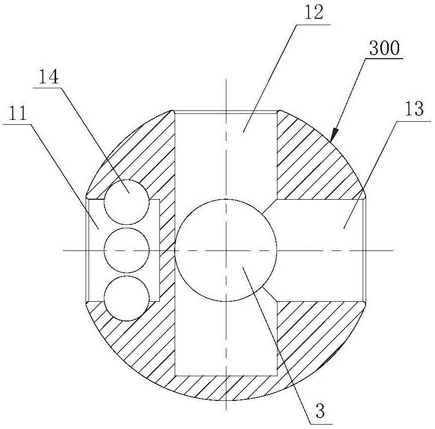
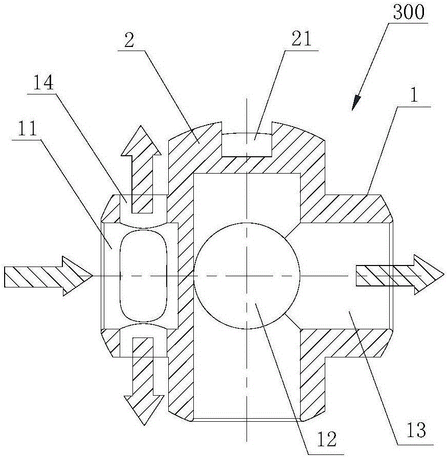
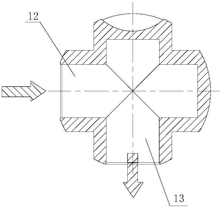
[0032] Such as Figure 1 to Figure 3 As shown, the fluid direction switching control 300 provided in this embodiment includes a control body 1 and a rotating member 2 . The control body 1 is spherical, and the side wall of the control body 1 has a first connection hole 11, a second connection hole 12, a third connection hole 13, and is formed on one side of the first connection hole 11 and communicates with the first connection hole 11 and the filter. At least one water outlet hole 14 outside the element 200, the first connection hole 11 and the second connection hole 12 are blocked by the control body 1, the first connection hole 11 and the third connection hole 13 are blocked by the control body 1, and the second connection hole 12 communicates with the third connection hole 13 through the inside of the control body 1 . The rotating member 2 is arranged on the upper part of the control body 1 and is connected with the external switch 400 to drive the control body 1 to rotat...

Embodiment 2

[0043] This embodiment is basically the same as Embodiment 1 and its variations, except that the backwash pre-filter provided in this embodiment is a straight-through backwash pre-filter (that is, there is no universal joint in the filter body). The backwash pre-filter of this embodiment includes a filter body 100', a filter element 200', a fluid direction switching control 300', a switching switch 400' and a drain valve 500'. The filter body 100' has a water inlet 101' and a water outlet 102'. The filter element 200' is disposed in the filter body 100'. The fluid direction conversion control 300' is arranged in the filter body 100' and connected with the filter element 200', so that water flows through the filter element 200' in opposite directions in the filtering state and the backwashing state. The changeover switch 400' is connected with the rotary groove 21' in the fluid direction changeover control 300'. The drain valve 500' is connected with the filter element 200'. ...


PUM


Abstract

The invention provides a flow direction changing controller and a backwash pre-filter. The flow direction changing controller comprises a spherical controller body and rotary part. The lateral wall of the controller body is provided with a first connecting hole, a second connecting hole, a third connecting hole and at least one water outlet formed in one side of the first connecting hole and communicating the first connecting hole and the outer side of a filter element. The first connecting hole and the second connecting hole are not communicated in the controller body, the first connecting hole and the third connecting hole are not communicated in the controller body, and the second connecting hole and the third connecting hole are communicated in the controller body. The rotary part is arranged on the upper portion of the controller body and connected with an external switching switch and drives the controller body to rotate. By arranging one flow direction changing controller which can change flow directions in the backwash pre-filter, the directions of water flow passing the filter element under the filtering state and the washing state of the backwash pre-filter are opposite, and an effect of forward filtering and reverse washing is achieved.

Description

technical field [0001] The invention relates to the technical field of filter structures, and in particular to a fluid direction conversion control and a backwash pre-filter. Background technique [0002] For a long time, secondary pollution such as rust, sediment, asbestos fibers, red worms, moss and algae produced in the process of civil tap water transportation cannot be solved. With the continuous improvement of living standards, human beings also have strict hygienic requirements for drinking water. A pre-filter will be installed in modern household water to avoid secondary pollution of water quality. The service life of drinking fountains, booster pumps and other water facilities. [0003] The pre-filters currently on the market mainly include laminated pre-filters, flush pre-filters, and siphon pre-filters. After these pre-filters are used for a period of time, impurities such as gravel and rust will accumulate and adhere to the filter screen, causing the filter scr...

Claims


Application Information

Patent Timeline
Patent Type & Authority Applications(China)
IPC IPC(8): B01D29/33B01D29/66B01D35/00
CPCB01D29/33B01D29/66B01D35/00
Inventor 吴伟锋
Owner 杭州甲质科技有限公司
Learn More