Multi-welding-machine coordinated control device and method and welding system

A technology of coordinated control and control devices, applied in welding equipment, welding accessories, manufacturing tools, etc., can solve problems affecting the coordination effect and achieve high anti-interference performance

Active Publication Date: 2016-11-16
PANASONIC WELDING SYST TANGSHAN
View PDF6 Cites 1 Cited by
  • Summary
  • Abstract
  • Description
  • Claims
  • Application Information

AI Technical Summary

Problems solved by technology

The AC coordination control device in this scheme has specified the input port and output port, the output port of the first welding machine must be connected with the input port of the second welding machine, the input port of the first welding machine must be connected with the second welding machine The output port is connected, this connection method determines that this scheme can only realize the coordinated welding of two welding machines, and this scheme can only realize the coordinated control of AC welding, with the same phase output, and if the coordination line is interfered, will affect the coordination

Method used


Image

  • Multi-welding-machine coordinated control device and method and welding system
  • Multi-welding-machine coordinated control device and method and welding system
  • Multi-welding-machine coordinated control device and method and welding system

Examples


Embodiment Construction

[0029] Example embodiments will now be described more fully with reference to the accompanying drawings. Example embodiments may, however, be embodied in many forms and should not be construed as limited to the examples set forth herein; rather, these embodiments are provided so that this disclosure will be thorough and complete and will fully convey the concept of example embodiments to those skilled in the art. The described features, structures, or characteristics may be combined in any suitable manner in one or more embodiments. In the following description, numerous specific details are provided in order to give a thorough understanding of embodiments of the present disclosure. However, those skilled in the art will appreciate that the technical solutions of the present disclosure may be practiced without one or more of the specific details being omitted, or other methods, components, devices, steps, etc. may be adopted. In other instances, well-known technical solution...


PUM


Abstract

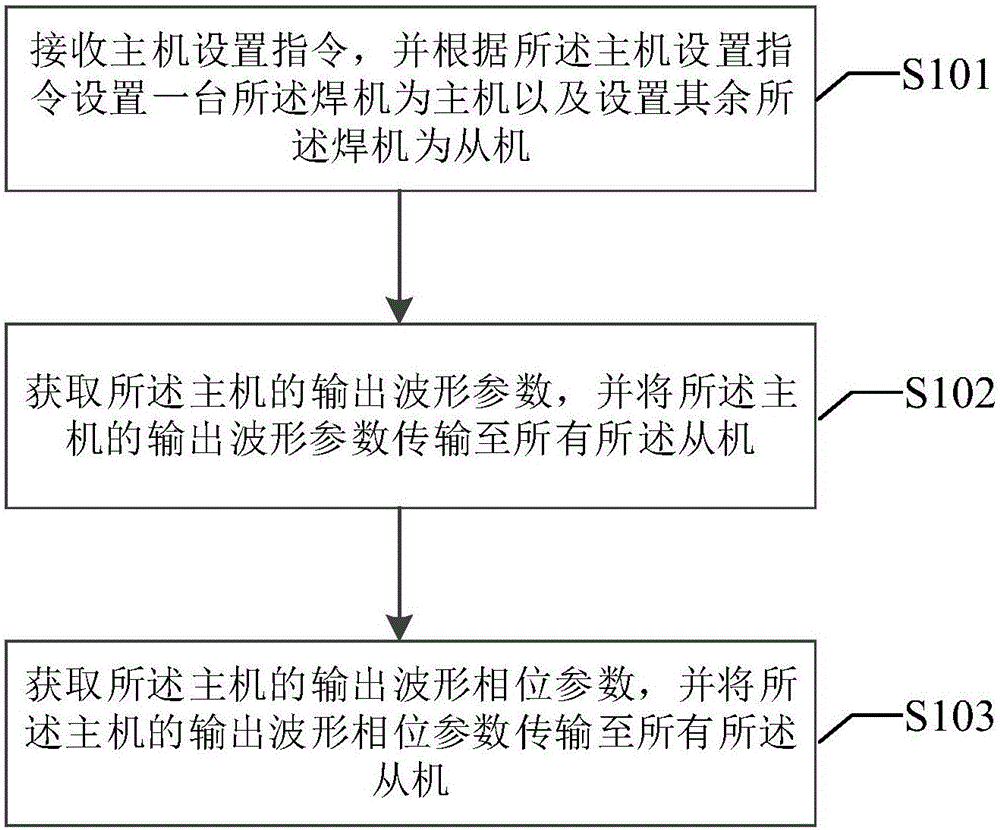
The invention provides a multi-welding-machine coordinated control device and method and a welding system. The multi-welding-machine coordinated control device comprises master-slave setting modules used for receiving master machine set instructions, setting any one of welding machines as a master machine and setting the rest of welding machines as slave machines according to the master machine set instructions, parameter transmission modules and phase position transmission modules. The parameter transmission module in the master machine is used for obtaining and outputting output waveform parameters of the master machine, and the parameter transmission modules in the slave machines are used for receiving the output waveform parameters output by the parameter transmission module in the master machine and transmitting the output waveform parameters to the slave machines where the parameter transmission modules are located. The phase position transmission module in the master machine is used for obtaining and outputting the output waveform phase position of the master machine, and the phase position transmission modules in the slave machines are used for receiving the output waveform phase position output by the phase position transmission module in the master machine and transmitting the output waveform phase position to the slave machines where the phase position transmission modules are located. According to the multi-welding-machine coordinated control device and method and the welding system, coordinated control output of alternating current and pulses of the multiple welding machines can be achieved, and synchronous output or fixed phase position difference asynchronous output can be achieved.

Description

technical field [0001] The present disclosure relates to the technical field of electric welding machines, and in particular, relates to a multi-welding machine coordination control device, a multi-welding machine coordination control method, and a welding system applying the multi-welding machine coordination control device. Background technique [0002] With the improvement of users' requirements on welding quality, welding speed and production output, the situation of multiple welding machines welding the same workpiece at the same time is increasing, and the problem of mutual interference between the arcs of multiple welding machines is also highlighted. Especially when the welding torches welded at the same time are very close on the same workpiece, or when the front and back sides of the same weld bead are welded at the same time, the mutual interference between the arcs will have a great impact on the welding effect and weld shape. Eventually lead to poor welding. ...

Claims


Application Information

Patent Timeline
Patent Type & Authority Applications(China)
IPC IPC(8): B23K9/10B23K9/32
CPCB23K9/1043B23K9/32
Inventor 韩勇李文举李松惠昭
Owner PANASONIC WELDING SYST TANGSHAN
Why Eureka
Try Eureka