
Center positioning device

A technology of positioning device and fixing seat, which is applied in the direction of metal processing equipment, metal processing, manufacturing tools, etc., can solve the problem that there is no positioning mechanism for the conveying line body, and achieve the effect of high positioning accuracy, positioning accuracy and stability, and accurate positioning

Active Publication Date: 2016-11-16
GUANGDONG HANDSOME INTELLIGENT EQUIP CO LTD
View PDF12 Cites 14 Cited by
  • Summary
  • Abstract
  • Description
  • Claims
  • Application Information

AI Technical Summary

Problems solved by technology

In the prior art, a positioning mechanism, such as a blocking cylinder, is usually provided in the conveying direction of the conveying line body, but there is no corresponding positioning mechanism on the side of the conveying line body

Method used


Image

  • Center positioning device
  • Center positioning device
  • Center positioning device

Examples


Embodiment Construction

[0020] The embodiments of the present invention will be described in detail below in conjunction with the drawings.

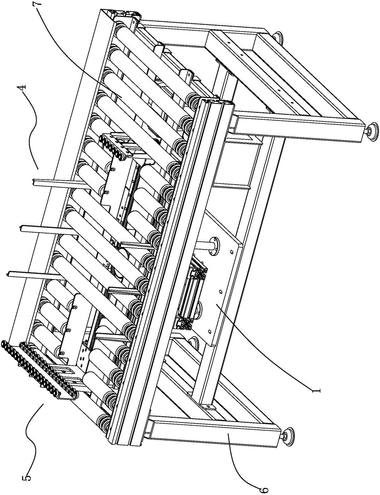
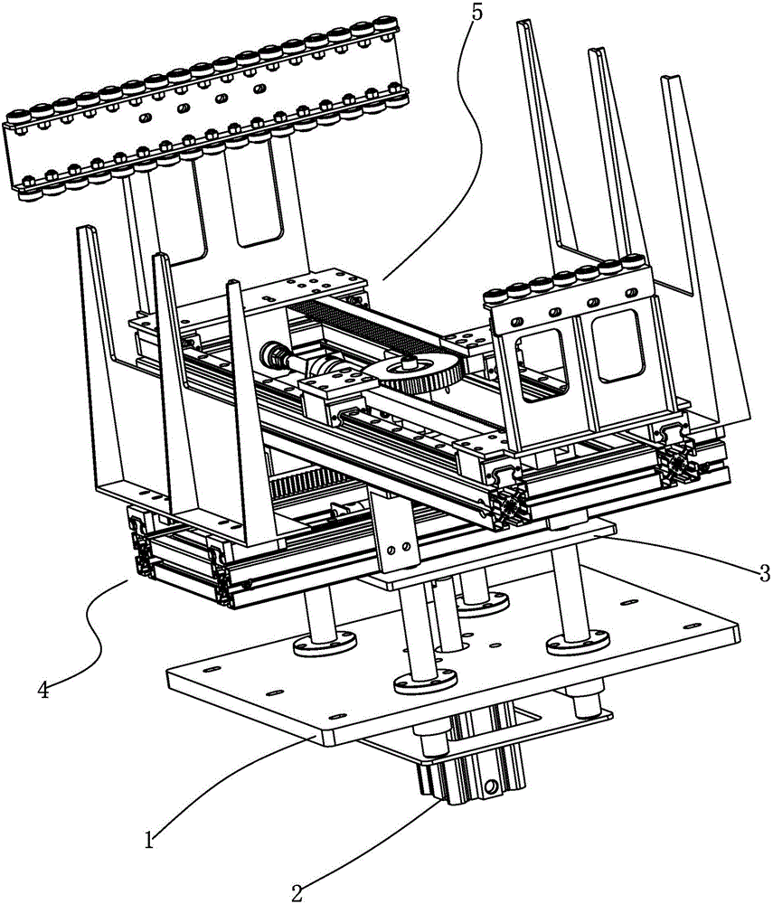
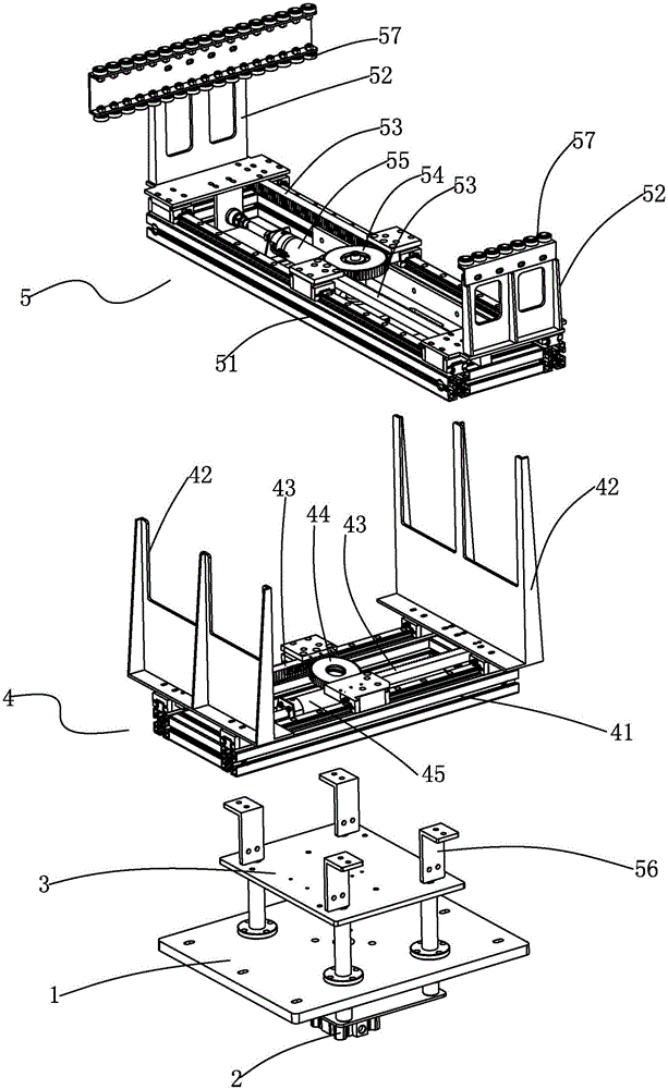
[0021] Such as figure 1 with figure 2 As shown, a centering positioning device of the present invention includes a frame 6 and an elevating fixing base 1 fixedly connected to the frame 6. The bottom of the elevating fixing base 1 is fixed with a lifting driving cylinder 2 arranged in a vertical direction. The output end of the lifting drive cylinder 2 penetrates the lifting fixing seat 1 and is fixedly connected with a lifting support plate 3, and the lifting support plate 3 is fixedly provided with a front and rear centering assembly 4 and a left and right centering assembly 5, the front and rear centering assembly 4 When centering and positioning the workpiece 8 with the left and right centering assembly 5, the output end of the lifting drive cylinder 2 is extended, so that the front and rear centering assembly 4 and the left and right centering assembly 5 both ...


PUM


Abstract

The invention discloses a center positioning device. A front-back centering module and a left-right centering module independent from each other are fixed on a lifting support plate; a lifting driving cylinder is controlled to enable the front-back centering module and the left-right centering module to extend out of the upper part of a frame and to perform automatic center positioning on front-back and left-right of workpieces to preset positions; and the front-back centering module and the left-right centering module perform auxiliary positioning. The center positioning device has the characteristics of high positioning precision and stability, and effectively guarantees smooth assembling.

Description

【Technical Field】 [0001] The invention relates to a positioning device, in particular to a centering positioning device. 【Background technique】 [0002] For automated production lines, when assembling products such as washing machines and refrigerators, the corresponding workpieces need to be accurately positioned for automatic assembly. In the prior art, a positioning mechanism, such as a blocking cylinder, is usually provided in the conveying direction of the conveying line body, but there is no corresponding positioning mechanism on the side of the conveying line body. Therefore, when the above positioning mechanism is used to position the workpiece, especially the larger workpiece, it is easy to shift position during the conveying process on the conveying line body, especially the push method is used for pushing and feeding, so it needs to be in the conveying line The assembly station of the body is equipped with an accurate positioning mechanism to ensure accurate positioni...

Claims


Application Information

Patent Timeline
Patent Type & Authority Applications(China)
IPC IPC(8): B23P19/00
CPCB23P19/006
Inventor 罗躜黄安全陶国帧李义李有然
Owner GUANGDONG HANDSOME INTELLIGENT EQUIP CO LTD
Learn More