
An Acoustic Emission Source Localization Method Without Wave Velocity Based on Dual Acoustic Emission Sensing Arrays and Beamforming

A technology of acoustic emission sensor and sensor array, which is applied in the field of acoustic emission source location that does not require wave velocity, non-destructive testing of engineering structures, and acoustic emission source location. problem, achieve the effect of overcoming speed dependence, stabilizing positioning accuracy, and realizing real-time monitoring and positioning

Inactive Publication Date: 2015-11-18
BEIHANG UNIV
View PDF9 Cites 0 Cited by
  • Summary
  • Abstract
  • Description
  • Claims
  • Application Information

AI Technical Summary

Problems solved by technology

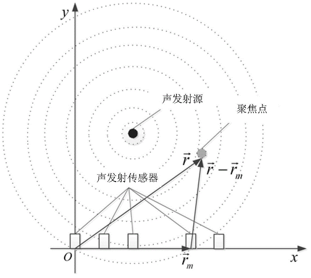
[0013] The beamforming method assumes that the acoustic emission wave propagates at a constant speed in the structure during the positioning process. However, due to the influence of dispersion, multi-mode, reflection, attenuation, etc., the wave speed will change, which directly affects the positioning of the acoustic emission source. precision
Moreover, the beamforming method is less affected by speed changes in the direction of the sensor array, and the positioning accuracy is higher, while the positioning accuracy is poorer in the vertical direction of the sensor.

Method used


Image

  • An Acoustic Emission Source Localization Method Without Wave Velocity Based on Dual Acoustic Emission Sensing Arrays and Beamforming
  • An Acoustic Emission Source Localization Method Without Wave Velocity Based on Dual Acoustic Emission Sensing Arrays and Beamforming
  • An Acoustic Emission Source Localization Method Without Wave Velocity Based on Dual Acoustic Emission Sensing Arrays and Beamforming

Examples


Embodiment Construction

[0043] In the following description, the present invention will be described in detail based on exemplary embodiments.

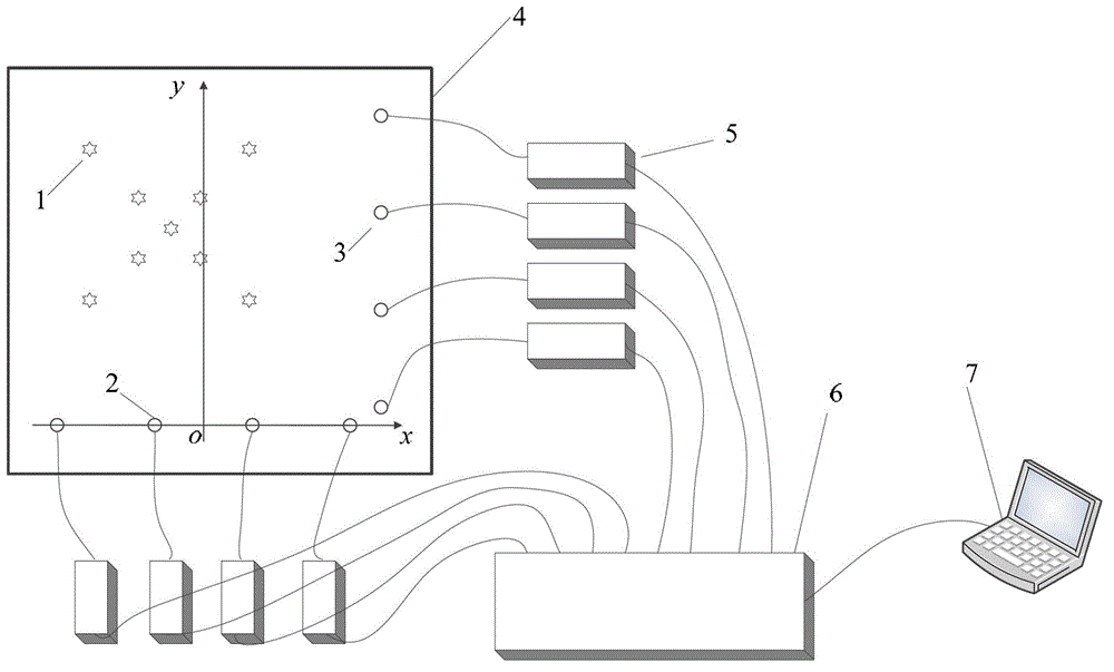
[0044] Such as image 3 As shown, the structure to be monitored is a uniform steel plate with a size of 500mm×500mm×5mm, and the occurrence of acoustic emission is simulated by breaking lead on the steel plate.

[0045] This example includes the following steps:

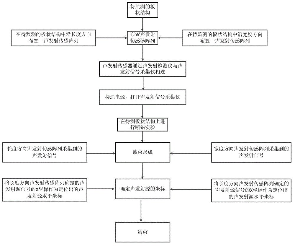
[0046] Such as figure 2 Shown is the flow chart of the method of the present invention. The following specific implementation steps are implemented according to this figure.

[0047] Step 1: If image 3 As shown, in the steel plate 4 to be monitored, the horizontal linear sensing array 2 is arranged along the horizontal direction, and the vertical acoustic emission sensing array 3 is arranged along the vertical direction. The acoustic emission sensing array includes 4 to 8 acoustic emission sensors. Take the direction of the horizontal linear acoustic emission sensing array as the X-axis, an...


PUM

PropertyMeasurementUnit
diameteraaaaaaaaaa
diameteraaaaaaaaaa

Abstract

The invention discloses a wave-velocity-free acoustic emission source locating method based on acoustic emission sensor arrays and wave beam formation. The method comprises (1) a step of arranging an acoustic emission sensor array in a plate-type structure to be monitored both along the length direction and along the width direction, and establishing a coordinate system by using the direction of the acoustic emission sensor array in the length direction as the X axis, using the direction of the acoustic emission sensor array in the width direction as the Y axis, and using the intersection of the two directions of the acoustic emission sensor arrays as the origin; (2) a step of connecting acoustic emission sensors in an acoustic emission signal detection system to an acoustic emission signal collecting device through front-end amplifiers; (3) a step of turning on a power source and the acoustic emission signal collecting device, and then performing pencil-lead-broken experiments, observing whether each channel waveform is normally displayed, and performing data collection if the channel waveforms are normally displayed; (4) a step of individually subjecting acoustic emission signals which are collected by the acoustic emission sensor array in the length direction and the acoustic emission sensor array in the width direction to wave beam formation; and (5) a step of using the X coordinates determined by the acoustic emission sensor array in the length direction as the horizontal coordinates, and using the Y coordinates determined by the acoustic emission sensor array in the width direction as the vertical coordinates.

Description

technical field [0001] The invention provides an acoustic emission source location method without wave velocity based on dual acoustic emission sensor arrays and beamforming, which relates to a non-destructive testing method for engineering structures, in particular to an acoustic emission source location method without wave velocity, which belongs to the acoustic Launch the field of non-destructive testing technology. technical background [0002] Various types of equipment widely use load-bearing plate or plate-like (such as shell) structures, such as aircraft fuselage, wings and hatches, rotary-wing aircraft fuselage and propeller blades, ship and submarine shells, liquid rockets Fuel storage tanks, etc. If this type of structure is damaged, it will have a negative impact on the overall performance of the equipment, and even lead to catastrophic equipment damage and casualties. Various non-destructive testing methods commonly used in engineering have their unique applic...

Claims


Application Information

Patent Timeline
Patent Type & Authority Patents(China)
IPC IPC(8): G01N29/26G01N29/14G01S5/18
Inventor 何田肖登红刘献栋单颖春于海生
Owner BEIHANG UNIV
Learn More