Adjusting device for workpiece clamping
A technology of adjusting device and workpiece clamp, which is applied to workpiece clamping devices, manufacturing tools, etc., can solve the problems of inconvenient rotation of the workpiece clamping device, and the clamping effect needs to be further improved, so as to achieve the effect of improving the clamping effect.
- Summary
- Abstract
- Description
- Claims
- Application Information
AI Technical Summary
Problems solved by technology
Method used
Image

Examples
Embodiment Construction
[0015] In order to make the object, technical solution and advantages of the present invention clearer, the present invention will be further described in detail below in conjunction with the accompanying drawings and embodiments. It should be understood that the specific embodiments described here are only used to explain the present invention, not to limit the present invention.
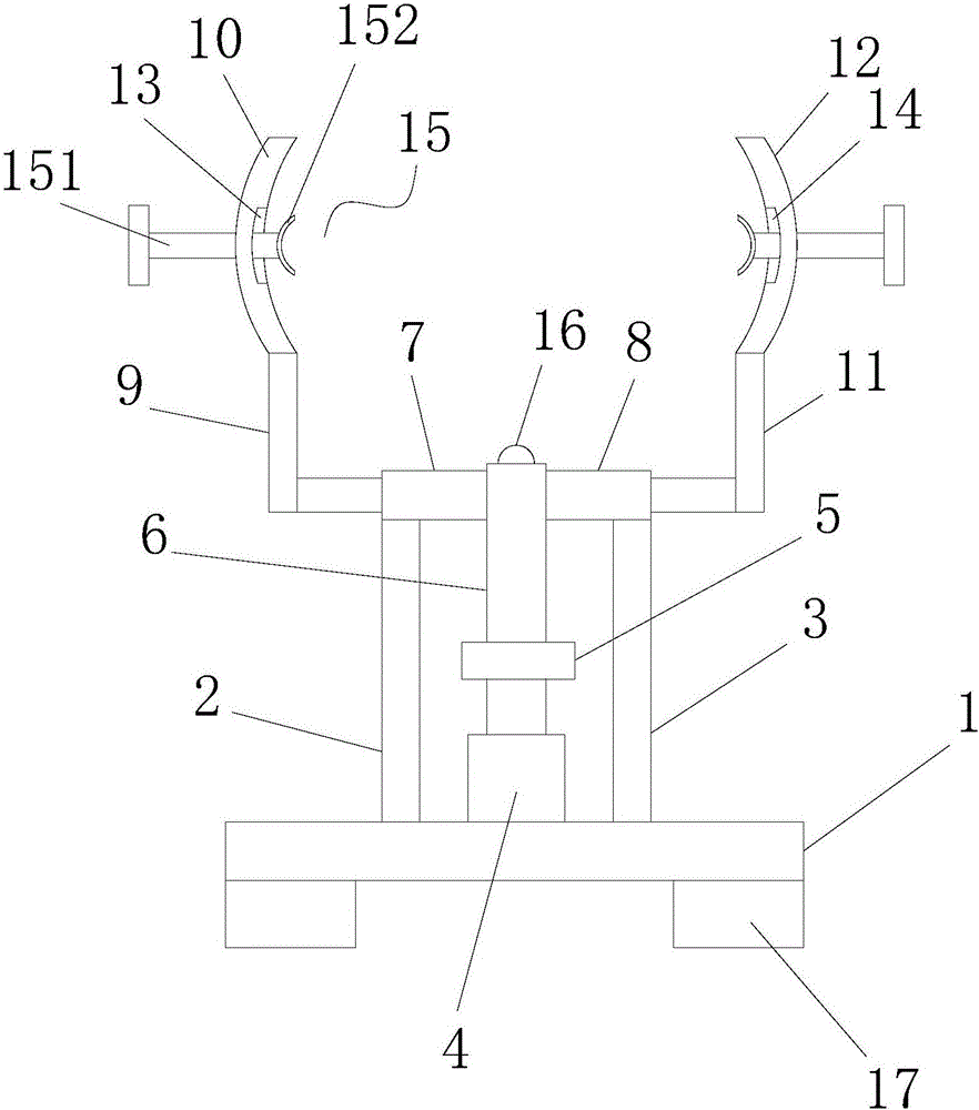
[0016] see figure 1 , figure 1 It is a structural schematic diagram of the present invention.
[0017] The adjustment device for workpiece clamping includes a base 1, a support rod A2 on one side of the base 1, a support rod B3 on the other side of the base 1, and a Motor 4, the output shaft of the motor 4 is connected to the rotating shaft 6 through a coupling 5, a hydraulic cylinder A7 is installed on one side of the rotating shaft 6, and a hydraulic cylinder is installed on the other side of the rotating shaft 6 B8; the top of the support rod A2 is connected to the hydraulic cylinder A7 for s...
PUM
 Abstract
Description
Claims
Application Information
 - Generate Ideas
- Intellectual Property
- Life Sciences
- Materials
- Tech Scout
- Unparalleled Data Quality
- Higher Quality Content
- 60% Fewer Hallucinations
Browse by: Latest US Patents, China's latest patents, Technical Efficacy Thesaurus, Application Domain, Technology Topic, Popular Technical Reports.
© 2025 PatSnap. All rights reserved.Legal|Privacy policy|Modern Slavery Act Transparency Statement|Sitemap|About US| Contact US: help@patsnap.com