Unmanned aerial vehicle wing changing mechanism with two wings capable of changing sweepback angles synchronously and coaxially in same plane

A technology of unmanned aerial vehicle and variable sweep, which is applied to unmanned aerial vehicles, aircrafts, motor vehicles and other directions, and can solve the problems of large driving torque and precise synchronous rotation of the wings on both sides, so as to facilitate control and reduce interference. Deflection moment, the effect of preventing height drop

Active Publication Date: 2016-11-16
BEIHANG UNIV
View PDF5 Cites 6 Cited by
  • Summary
  • Abstract
  • Description
  • Claims
  • Application Information

AI Technical Summary

Problems solved by technology

The crank-rocker mechanism drives the rotation of the wings on both sides by the rotation of the crank. There are single-crank and double-rocker forms and double-crank and double-rocker forms. General

Method used


Image

  • Unmanned aerial vehicle wing changing mechanism with two wings capable of changing sweepback angles synchronously and coaxially in same plane
  • Unmanned aerial vehicle wing changing mechanism with two wings capable of changing sweepback angles synchronously and coaxially in same plane
  • Unmanned aerial vehicle wing changing mechanism with two wings capable of changing sweepback angles synchronously and coaxially in same plane

Examples


Embodiment Construction

[0021] The present invention will be described in detail below in conjunction with the accompanying drawings and embodiments.

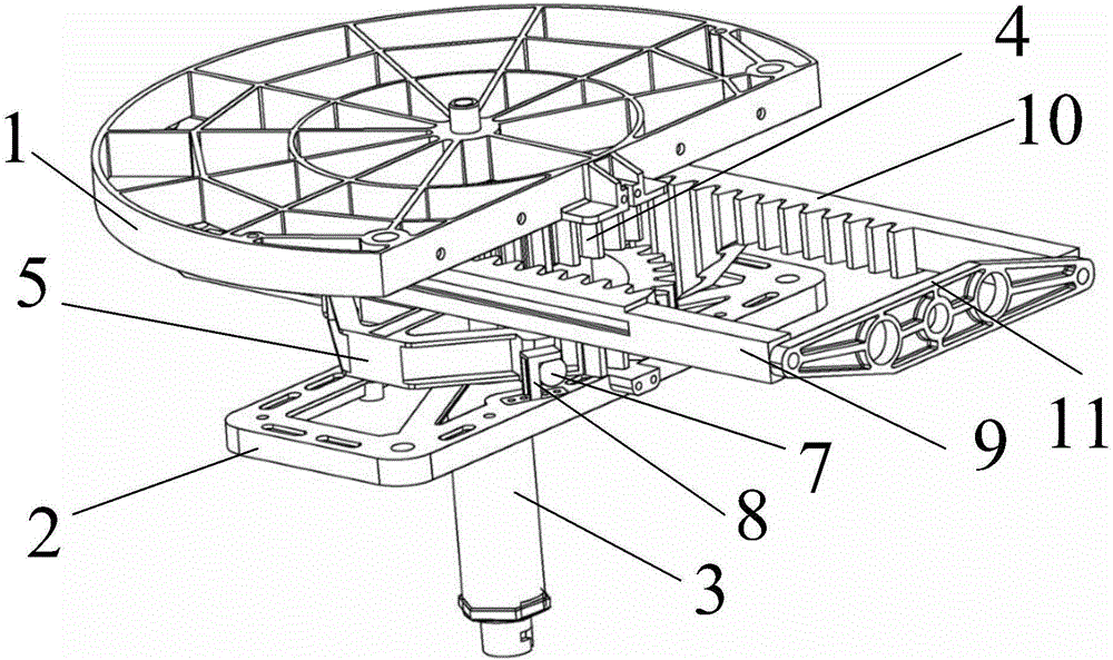
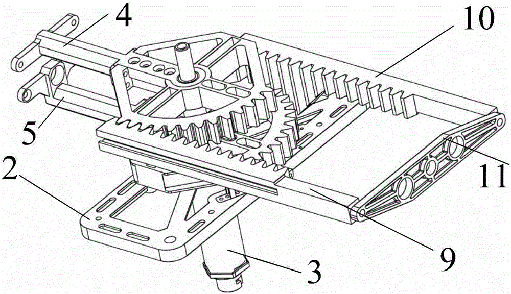
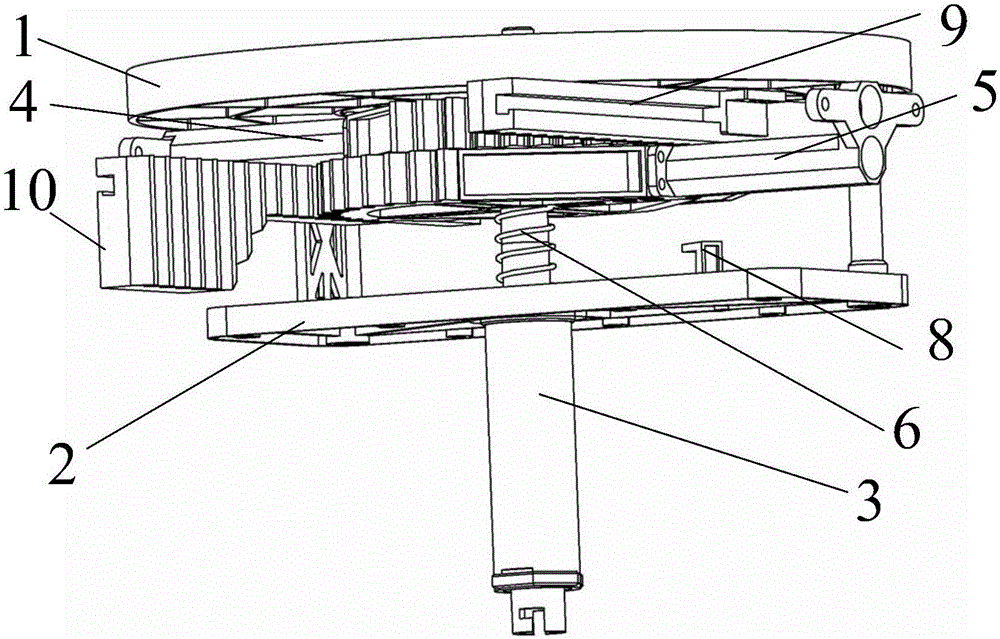
[0022] In order to reduce the storage space of the variable-wing UAV, it is necessary to realize that the left and right wings are completely swept back and stacked up and down before the UAV is launched. In the folded state, the left and right wings should be misplaced up and down. In the unfolded state, in order to keep the left and right wings on the same plane, and in order to follow the principle of "synchronization, coaxiality, and same plane", it is necessary to make the lower side of the wing when stacked. Wings realize lifting motion. Therefore, the present invention designs a special left and right wing stacked up and down structure and a drive structure to realize the fast lifting motion of the wing and ensure that the left and right wings are on the same plane when the wing is unfolded.

[0023] The invention provides a wing-changing mech...


PUM


Abstract

The invention discloses an unmanned aerial vehicle wing changing mechanism with two wings capable of changing sweepback angles synchronously and coaxially in the same plane and belongs to the technical field of unmanned aerial vehicle structural design. The unmanned aerial vehicle wing changing mechanism comprises an upper supporting board, a lower supporting board, a rotary haft, a right wing support, a left wing support, a spring, a protruding block, a limiting hook, a rack A and a rack B. The rotary shaft is connected with the lower supporting board, the left wing support, the right wing support and the upper supporting board from bottom to top. The spring is arranged between the left wing support and the lower supporting board. The rotary shaft is sleeved with the spring. By the adoption of the unmanned aerial vehicle wing changing mechanism, wings of an unmanned aerial vehicle can be folded to be stored, the storage space is reduced, and the wings can be barreled; the wings can be rapidly unfolded in the launching stage of the unmanned aerial vehicle, lift force can be established rapidly, and the situation that the height of the unmanned aerial vehicle is reduced, and even the unmanned aerial vehicle crashes can be effectively prevented; the two wings of the unmanned aerial vehicle are changed synchronously and coaxially all the time, the two wings are located on the same plane rapidly after the unmanned aerial vehicle is launched, the interference yawing moment in the transverse lateral direction can be reduced as much as possible, and control is convenient.

Description

technical field [0001] The invention belongs to the technical field of structural design of unmanned aerial vehicles, and specifically relates to a wing-changing mechanism of an unmanned aerial vehicle that can synchronously change the sweep angle of two wings on the same axis and in the same plane. Background technique [0002] Certain UAVs require a small footprint for storage and launch, which requires their wings to be fully folded before takeoff. After take-off, the wings need to be deployed rapidly to provide lift. In order to enable the aircraft to change its aerodynamic shape in real time during flight, the sweepback mechanism of the aircraft must be able to realize stepless adjustment and position holding functions, that is, the sweep angle must be able to maintain any angular position within the working range. [0003] Throughout the development history of aircraft, the variant with variable sweep is the most commonly used and most successful variant. Since the 19...

Claims


Application Information

Patent Timeline
IPC IPC(8): B64C3/40
CPCB64C3/40B64U30/12
Inventor 吴森堂卜凡姚征张杰
Owner BEIHANG UNIV
Why Eureka
Try Eureka