Supercharge Your Innovation With Domain-Expert AI Agents!

Shaft bending test device

A test device and shaft technology, used in measuring devices, using stable bending force to test material strength, instruments, etc., can solve problems such as shortening the service life of test equipment, affecting test efficiency and results, and test equipment without protective cover. , to achieve the effect of small space occupancy, prevention of injury, and high test efficiency

Active Publication Date: 2019-04-12
耐世特凌云驱动系统(涿州)有限公司
View PDF10 Cites 0 Cited by
  • Summary
  • Abstract
  • Description
  • Claims
  • Application Information

AI Technical Summary

Problems solved by technology

[0003] At present, the friction welding performance test is carried out through a device for material strength testing. The testing machine is composed of three beams and two columns. Special test equipment, using this kind of experimental equipment requires a lot of time for test preparation, which affects the test efficiency and results. The test equipment uses sensors to measure force. Because there are convex rounds at the solder joints of the hollow shaft, the convex rounds are easy to cause damage to the sensor, shortening the test equipment. The service life of the test equipment is long, and the test equipment has no protective cover, and the exposure of the workpiece will easily cause safety problems during the test process. In addition, a piece of equipment is used for both hollow shaft friction welding performance tests and other material strength tests. With the Volkswagen MQB series The output of products has increased, and the use of this test equipment is far from meeting the needs of testing and testing. It is necessary to develop a special test equipment

Method used


Image

  • Shaft bending test device
  • Shaft bending test device
  • Shaft bending test device

Examples


Embodiment Construction

[0015] The present invention will be further described in detail below in conjunction with the accompanying drawings and specific embodiments.

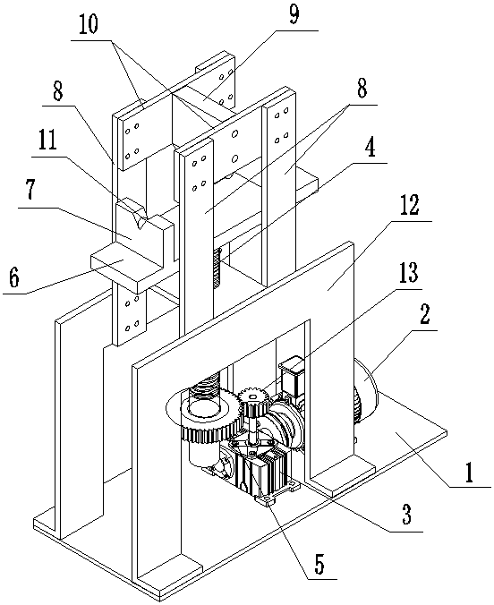
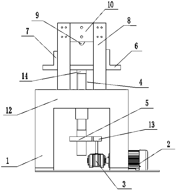
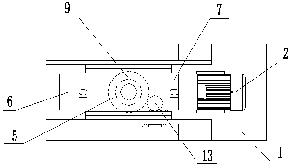
[0016] Such as figure 1 , figure 2 , image 3 and Figure 4 Shown, the present embodiment comprises bottom bracket 1, working platform 6, upper crossbeam 10, two groups of every group more than two columns 8, two V-shaped support blocks 7, top 9 and the lifting device of working platform. Preferably, the bottom bracket 1, the working platform 6, the upper beam 10, the column 8, the two V-shaped support blocks 7 and the top 9 are made of materials with good rigidity, such as Q235A. Two groups of columns 8 are relatively fixed on two beams 12 at the upper end of the bottom bracket 1 by M10 bolts. There is a horizontal working platform 6 between the lower parts. The two opposite faces of the group column 8 are vertical V-shaped support blocks 7 . Each group column 8 upper end is fixed with upper beam 10 by M10 bolt, is fixed with t...


PUM

PropertyMeasurementUnit
angleaaaaaaaaaa

Abstract

The invention discloses a shaft lever bending testing device. The device comprises a bottom bracket, an operating platform, upper beams, two groups of vertical columns, two V-shaped supporting blocks, a center and a lifting device for the operating platform, wherein each group of vertical columns comprise more than two vertical columns; the two groups of vertical columns are oppositely fixed on two beams at the upper ends of the bottom bracket; the horizontal operating platform is arranged between the lower parts of the two vertical columns; the V-shaped supporting blocks which are arranged in parallel and perpendicular to the two opposite surfaces of the two groups of vertical columns are respectively fixed at the two ends of the upper end surface of the operating platform; the upper beams are fixed at the upper ends of each group of upper beams; the center is fixed between two upper beams; the lower end of the center is dead against the connecting line between V-shaped openings of the two V-shaped supporting blocks; the center of the lower end of the operating platform is fixed on the upper end surface of the lifting device for the operating platform. The device has the advantages that a rotate speed of a stepper motor is adjustable, the testing efficiency is high, the device is stable and reliable, and the safety is high; sensors are not provided, the testing device is not easy to damage, the floor space is small, and the device is simple, convenient and efficient to operate.

Description

technical field [0001] The invention relates to a test device, in particular to a test device for testing the friction welding performance of hollow shaft rods, which is mainly used for testing the friction welding performance of Volkswagen MQB series hollow shafts. Background technique [0002] Volkswagen MQB series hollow shaft involves a key process in the machining process - friction welding. The welding strength of friction welding directly affects the life of the whole shaft, and even affects the performance of the whole shaft and the normal driving of the vehicle, seriously endangering personal safety. Therefore, it is necessary to study a reliable test device to verify the strength of friction welding. [0003] At present, the friction welding performance test is carried out through a device for material strength testing. The testing machine is composed of three beams and two columns. Special test equipment, using this kind of experimental equipment requires a lot ...

Claims


Application Information

Patent Timeline
Patent Type & Authority Patents(China)
IPC IPC(8): G01N3/20G01N3/02
CPCG01N3/02G01N3/20G01N2203/0062G01N2203/027
Inventor 张麟现王俊孙巍孟凡奎高婧
Owner 耐世特凌云驱动系统(涿州)有限公司
Features
  • R&D
  • Intellectual Property
  • Life Sciences
  • Materials
  • Tech Scout
  • Unparalleled Data Quality
  • Higher Quality Content
  • 60% Fewer Hallucinations
Learn More