Projection imaging system

An imaging system and a technology for projecting images, applied in the field of projection, can solve the problems of low resolution of the projection imaging system, and achieve the effects of improving the imaging quality, improving the delicate feeling, and improving the resolution.

Active Publication Date: 2016-11-16
QINGDAO HISENSE LASER DISPLAY CO LTD
View PDF4 Cites 11 Cited by
  • Summary
  • Abstract
  • Description
  • Claims
  • Application Information

AI Technical Summary

Problems solved by technology

[0005] In order to solve the problem of low resolution of the projection imaging system existing in the related art, the present invention provides a projection imaging system

Method used


Image

  • Projection imaging system
  • Projection imaging system
  • Projection imaging system

Examples


Embodiment 1

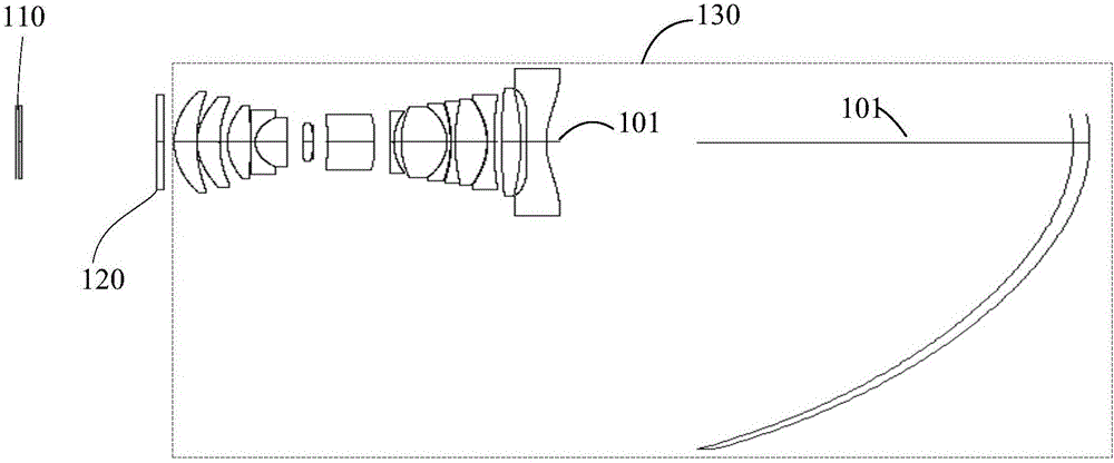
[0020] An embodiment of the present invention provides a projection imaging system, figure 1 is a schematic diagram of the projection imaging system, such as figure 1 As shown, the projection imaging system sequentially includes a light valve 110, a vibrating mirror 120, and a projection lens 130 along the optical path where the image beam exits, and the center of the light valve 110 is offset from the optical axis 101 of the projection lens 130;

[0021] Further, the light valve 110 is used to modulate the light beam transmitted from the light source system in the projector, so that the light valve 110 generates an image beam, and directs the image beam to the vibrating mirror 120;

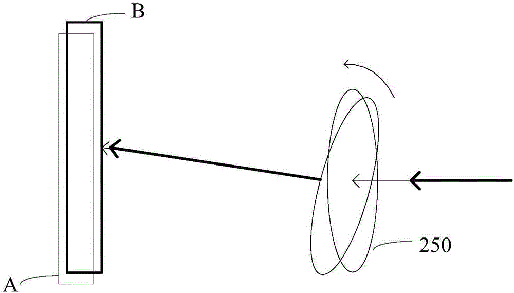
[0022] The vibrating mirror 120 vibrates so that the image beams corresponding to two adjacent frames of projected images passing through the vibrating mirror 120 do not completely overlap, and the image beams corresponding to the adjacent two frames of projected images are sequentially directed ...

Embodiment 2

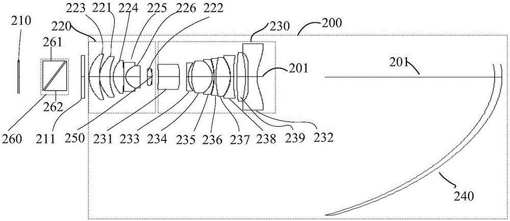
[0026] Another embodiment of the present invention provides a projection imaging system, figure 2 is a projection imaging system such as figure 2 As shown, the projection imaging system includes: a light valve 210 , a vibrating mirror 211 and a projection lens 200 .

[0027] The light valve 210 is used for modulating the beam transmitted from the light source system in the projector, so that the light valve 210 generates an image beam and directs the image beam to the vibrating mirror 211 .

[0028] Optionally, the light valve 210 is a digital micromirror device (English: Digital Micromirror Device, DMD for short), and the DMD may have a resolution of 2K or 3K.

[0029] In addition, the light valve 210 includes a reflective mirror array and a control circuit. When the light valve 210 is illuminated, the control circuit controls the reflective mirror array to reflect the light beam emitted by the light source system to generate an image light beam. How the light valve 210 s...


PUM


Abstract

The invention discloses a projection imaging system and belongs to the technical field of projection. The projection imaging system can help resolve a problem that a conventional projection imaging system adopting relevant technologies is low in resolution. The projection imaging system orderly comprises a light valve, a vibration lens and a projection lens along an optical path in which image light beams are emitted; the center of the light valve is biased on an optical axis of the projection lens; the light valve is used for modulating a light beam, transmitted from a light source system, in a projector; then the light valve is enabled to generate the image light beams, and the image light beams are emitted toward the vibration lens; via vibration of the vibration lens, the image light beams, going through the vibration lens, corresponding to two neighboring frames of projection images cannot be completely superposed onto each other; the image light beams corresponding to the two neighboring frames of projection images are orderly projected toward the projection lens; when the image light beams are projected toward the projection lens from the vibration lens, the projection lens is used for correcting and amplifying the image light beams, and the corrected and amplified image light beams are projected onto a projection screen.

Description

technical field [0001] The invention relates to the field of projection technology, in particular to a projection imaging system. Background technique [0002] With the improvement of science and technology, projection imaging systems are more and more widely used in people's work and life, such as education, office, home or entertainment. For example, for projection imaging systems used in home theaters, the resolution of projection imaging systems is higher. High, the user experience is higher. Therefore, people have higher and higher requirements for projection imaging systems. [0003] In related technologies, ultra-short-focus projection equipment tends to be used in household projection equipment. The ultra-short-focus projection imaging system includes: a light valve, a lens group and a mirror; wherein, the light valve is used to generate an image beam, and the image beam first enters the lens group , the lens group forms an image of the image beam, and then passes ...

Claims


Application Information

Patent Timeline
Patent Type & Authority Applications(China)
IPC IPC(8): G02B13/18G02B13/00G03B21/14
CPCG02B13/0045G02B13/18G03B21/142
Inventor 李晓平阴亮
Owner QINGDAO HISENSE LASER DISPLAY CO LTD
Why Eureka
Try Eureka