DC contactor

A DC contactor and dynamic contact technology, applied in the direction of relays, electromagnetic relays, electromagnetic relay details, etc., can solve problems such as limited thickness of insulating bushings, limited dielectric withstand voltage, equipment failure, etc., to reduce breakdown and damage risk, increased application range, effect of increased creepage distance

Active Publication Date: 2016-11-16
昆山国力源通新能源科技有限公司
View PDF7 Cites 2 Cited by
  • Summary
  • Abstract
  • Description
  • Claims
  • Application Information

AI Technical Summary

Problems solved by technology

[0003] In this structure, although the metal core rod and the static contact piece are connected by the insulating bushing 112, there is inevitably a gap between the insulating bushing and the insulating washer, and the creepage distance between the metal core rod 107 and the moving contact piece 104 That is, the thickness of the insulating bushing, due to the limited thickness of the insulating bushing, the dielectric withstand voltage between the metal core rod 107 and the moving contact piece 104 is limited, which limits the application range of the product, and it is difficult to adapt to the harsh working environment. Equipment failures such as breakdown and damage occur, which will affect the service life of the contactor

Method used


Image

  • DC contactor
  • DC contactor
  • DC contactor

Examples


Embodiment Construction

[0028] In conjunction with the accompanying drawings, the present invention is described in detail, but the scope of protection of the present invention is not limited to the following examples, that is, all simple equivalent changes and modifications made with the patent scope of the present invention and the content of the specification are still patents of the present invention. covered.

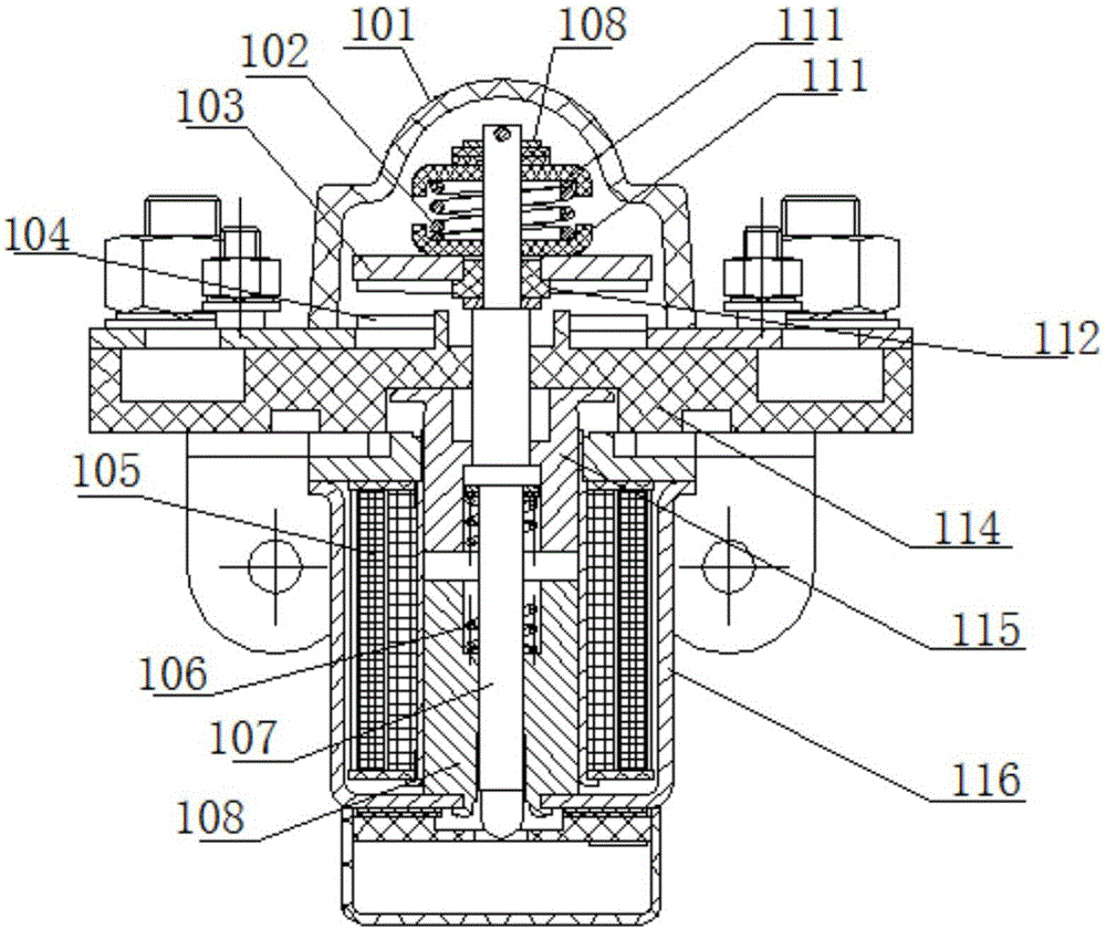
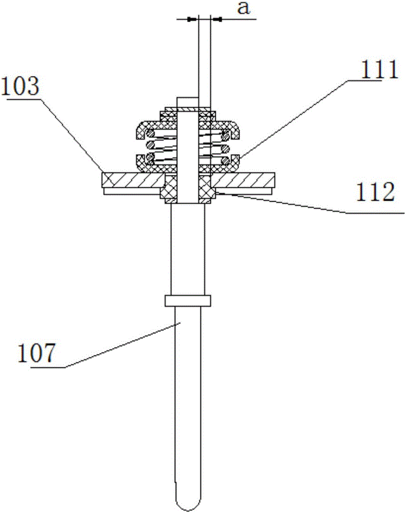
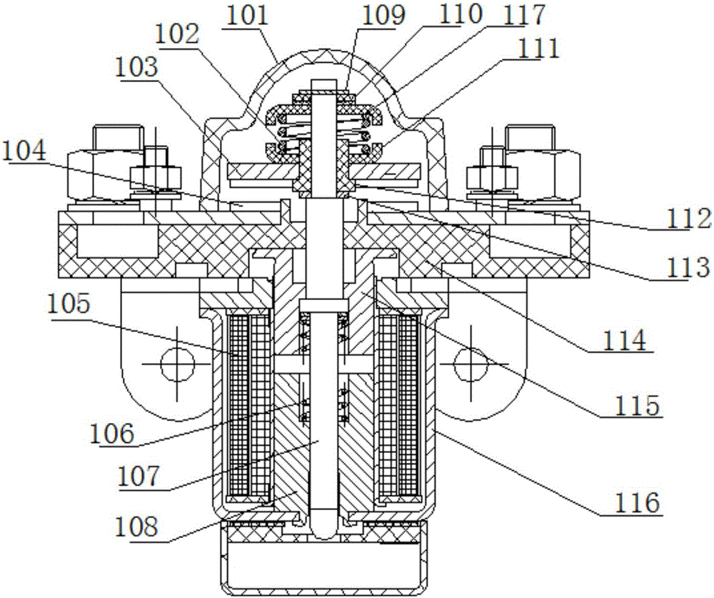
[0029] refer to Figure 3-4 , is a DC contactor according to the present invention, including a metal shell 116 and a plastic seat plate 114 fixed on the upper opening of the metal shell, a pair of static contact points 104 are fixed on the upper side of the plastic seat plate and play a sealing role The cap 101, the metal core rod 107 is vertically movable and placed in the plastic seat plate 114, the upper end of the metal core rod 107 extends into the cap 101, and the lower end extends into the metal shell 116, and the upper end of the metal core rod is fixed with The moving contact p...


PUM


Abstract

The invention discloses a DC contactor, and the DC contactor comprises a metal housing, a plastic bottom plate, a static contact, a cap cover, a metal core bar, a movable contact piece, and an electromagnet assembly. The upper end of the metal core bar is located above the movable contact piece and is provided with a lower insulating washer and an upper insulating washer at an interval. A pressure spring is disposed between the upper and lower insulating washers, and the upper end of the metal core bar is fixedly provided with an insulating lining. The longitudinal height of the insulating lining is equal to the sum of the height of the movable contact piece and the height of the lower insulating washer. The movable contact piece is fixed on the lower peripheral surface of the insulating lining, and the lower insulating washer is fixed on the upper peripheral surface of the insulating lining. The DC contactor increases the height of the insulating lining, and enables the insulating lining to pass through the insulating washers, thereby increasing the creep distance of the metal core bar, finally improving the dielectric withstand voltage between the movable contact piece and the metal housing, enabling a product to be used in a high-dielectric environment, greatly enlarging the application range of the product, reducing the breakdown and damage risks, and prolonging the service life of the DC contactor.

Description

technical field [0001] The invention relates to a DC contactor. Background technique [0002] Existing DC contactors, see Figure 1-2 , including a metal shell 116 and a plastic seat plate 114 fixed to the upper opening of the metal shell 116, a static contact point 104 and a cap 101 are fixed on the side of the plastic seat plate, and the metal core rod 107 is movably inserted in the plastic seat along the longitudinal direction In the plate 114, the upper end of the metal core rod 107 extends into the cap 101, and the lower end extends into the metal shell 116. The upper end of the metal core rod 107 is fixed with the movable contact piece 103 through the insulating bush 113, and the movable contact piece is located at the static contact point. Above, the lower end of the metal core rod 107 is provided with a moving iron core 115, a return spring 106 and a static iron core 108 in sequence. The moving iron core 115 is fixedly connected to the metal core rod, and the end of ...

Claims


Application Information

Patent Timeline
Patent Type & Authority Applications(China)
IPC IPC(8): H01H50/02
CPCH01H50/026H01H2050/028
Inventor 张承盛吴芳潘乔旭刘杰
Owner 昆山国力源通新能源科技有限公司
Why Eureka
Try Eureka