A torque-increasing permanent magnet retarder

A retarder, permanent magnet technology, applied in the direction of permanent magnet clutch/brake, electric brake/clutch, electromechanical device, etc., can solve the problems of power consumption of automobile, difficult grading control, magnetic field cannot be completely shielded, etc. The effect of braking torque, reasonable structure design and cost saving

Active Publication Date: 2019-04-16
SHANDONG JIAOTONG UNIV
View PDF5 Cites 0 Cited by
  • Summary
  • Abstract
  • Description
  • Claims
  • Application Information

AI Technical Summary

Problems solved by technology

But there is a disadvantage that the magnetic field cannot be completely shielded, so the traditional permanent magnet retarder will consume a part of the power of the car as long as the rotor rotates.
At the same time, the permanent magnet retarder also has the shortcomings of insufficient braking torque and difficult to achieve hierarchical control, which largely limits the market popularity of the permanent magnet retarder

Method used


Image

  • A torque-increasing permanent magnet retarder
  • A torque-increasing permanent magnet retarder

Examples


Embodiment Construction

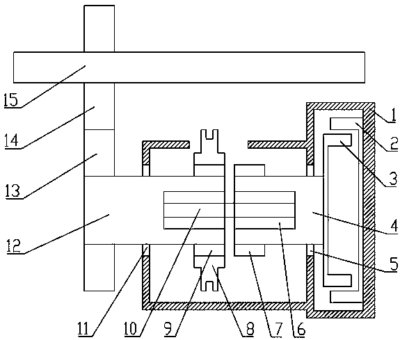
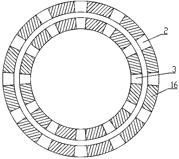
[0022] Attached below figure 1 , 2 A torque-increasing permanent magnet retarder of the present invention is described in detail below.

[0023] as attached figure 1 , 2 As shown, a torque-increasing permanent magnet retarder of the present invention has a structure comprising a housing 1, a stator 2, a rotor 3, a rotor shaft 4 and a combination assembly;

[0024] The stator 2 is circular, the first end of which is fixedly installed in the housing 1, and the second end extends to the outer ring of the rotor 3, and is in clearance fit with the rotor 3;

[0025] The rotor shaft 4 is rotatably mounted on the housing 1 through the second bearing 5, one end of which extends into the interior of the stator 2, and the rotor shaft 4 is coaxial with the stator 2;

[0026] The rotor 3 is circular, fixedly mounted on the end of the rotor shaft 4 close to the stator 2, and coaxial with the rotor shaft 4;

[0027] The combined assembly includes a driven shaft 12, a first combined gear...


PUM


Abstract

The invention relates to a permanent-magnet retarder, in particular to a torque-increasing permanent-magnet retarder. The torque-increasing permanent-magnet retarder comprises a shell, a stator, a rotor, a rotor shaft and a combination assembly, wherein the combination assembly comprises a driven shaft, a first combination gear, a combination sleeve and a second combination gear, the combination sleeve can be arranged on the first combination gear in a sliding way, permanent-magnet structures are arranged on adjacent surfaces of the stator and the rotor and attract to each other, and a fact that a braking torque is obtained by a mode of cutting a magnetic induction line of a traditional permanent-magnet buffer through a magnetic conduction material is changed to a fact that the braking torque is obtained by direct attraction between permanent magnets. By the combination assembly, the connection / disconnection of power transfer is achieved, and the problem of power loss generally existing in the permanent-magnet retarder brought by magnetic leakage is solved; and meanwhile, by matching a rotor structure and a stator structure which is separately provided with the permanent magnets, the braking torque is increased, the usage number of the permanent magnets is greatly reduced on the condition of acquiring the same braking torque, and the cost is saved.

Description

technical field [0001] The invention relates to an automobile retarder, in particular to a permanent magnet retarder. Background technique [0002] Automobile retarder is a kind of automobile braking auxiliary device. At present, it is mainly electric eddy current retarder and hydraulic retarder. Other forms of retarder include permanent magnet retarder, self-excited retarder and so on. Among them, the permanent magnet retarder has the advantages of small size, light weight, and no energy consumption, so it has been paid more and more attention. [0003] At present, both domestic and foreign permanent magnet retarders use demagnetization to terminate the working state of the retarder. The degaussing method is generally to move or dislocate the magnet, and use magnetic materials to shield the magnetic force lines. But this has a disadvantage that the magnetic field cannot be completely shielded, so that the traditional permanent magnet retarder will consume a part of the pow...

Claims


Application Information

Patent Timeline
Patent Type & Authority Patents(China)
IPC IPC(8): H02K49/10
CPCH02K49/102
Inventor 衣丰艳吕国仁吕志明杨君王健刘永辉周长峰何仁张立伟艾晓飞
Owner SHANDONG JIAOTONG UNIV
Why Eureka
Try Eureka