A permanent magnet retarder that can automatically adjust the braking torque

A braking torque and automatic adjustment technology, applied in electric brakes/clutches, permanent magnetic clutches/brakes, electric components, etc., to achieve reasonable structural design, solve power consumption, and reduce control operations

Active Publication Date: 2018-09-21
SHANDONG JIAOTONG UNIV
View PDF5 Cites 0 Cited by
  • Summary
  • Abstract
  • Description
  • Claims
  • Application Information

AI Technical Summary

Problems solved by technology

[0004] The present invention provides a permanent magnet retarder that can automatically adjust the braking torque for the above problems of hierarchical control

Method used


Image

  • A permanent magnet retarder that can automatically adjust the braking torque
  • A permanent magnet retarder that can automatically adjust the braking torque
  • A permanent magnet retarder that can automatically adjust the braking torque

Examples


Embodiment Construction

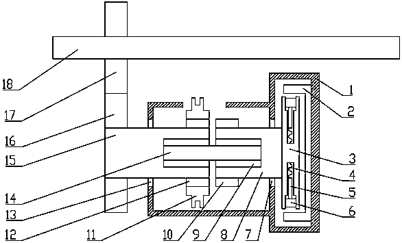
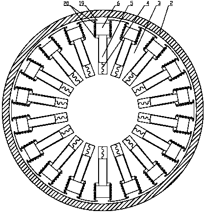
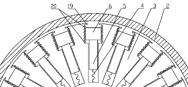
[0030] Attached below figure 1 , 2 3. A permanent magnet retarder that can automatically adjust the braking torque of the present invention will be described in detail below.

[0031] as attached figure 1 , 2 , 3, a permanent magnet retarder that can automatically adjust the braking torque of the present invention mainly includes a housing 1, a stator 2, a rotor disk 3, a rotor shaft 8, a sliding magnet assembly and a combination assembly;

[0032] The stator 2 is circular, the first end of which is fixedly installed in the housing 1, the second end extends to the outer ring of the rotor disk 3, and is in clearance fit with the rotor disk 3;

[0033] The rotor shaft 8 is rotatably mounted on the housing 1 through the second bearing 7, one end of which extends into the interior of the stator 2, and the rotor shaft 8 is coaxial with the stator 2;

[0034] The rotor disk 3 is fixedly installed on the end of the rotor shaft 8 close to the stator 2, and is coaxial with the roto...


PUM


Abstract

The invention comprises a permanent magnet retarder for automatically adjusting braking torque, the retarder mainly comprises a shell, a stator, a rotor disc, a rotor shaft and combination components, wherein the rotor disc comprises multiple groups of spring magnet components; the combination components comprises a driven shaft, a first combination gear, a combination sleeve and a second combination gear, the driven shaft has the same axis with the rotor shaft, the first combination gear is arranged on one end of the driven shaft near the rotor shaft, and the second combination gear is arranged on one side of the rotor shaft near the driven shaft; the combination sleeve is slidably arranged on the first combination gear; the spring magnet components comprises permanent magnets, sliding shafts, springs, balls and positioning blocks, the permanent magnets are connected to the rotor disc through the sliding shafts and the springs in sequence, and the permanent magnets can axially move along the arraying direction of balls. According to the invention, combination components are adopted to realize disconnection and connection of power transmission, a power loss problem caused by flux leakage which is ubiquitous in the permanent magnet retarder can be solved, and automatic adjustment of the braking torque can be realized through cooperating with the spring magnet components.

Description

technical field [0001] The invention relates to an automobile retarder, in particular to a permanent magnet retarder. Background technique [0002] Automobile retarder is a kind of automobile braking auxiliary device. At present, it is mainly electric eddy current retarder and hydraulic retarder. Other forms of retarder include permanent magnet retarder, self-excited retarder and so on. Among them, the permanent magnet retarder has the advantages of small size, light weight, and no energy consumption, so it has been paid more and more attention. [0003] At present, both domestic and foreign permanent magnet retarders use demagnetization to terminate the working state of the retarder. The degaussing method is generally to move or dislocate the magnet, and use magnetic materials to shield the magnetic induction line. But this has a disadvantage that the magnetic field cannot be completely shielded, so that the traditional permanent magnet retarder will consume a part of the ...

Claims


Application Information

Patent Timeline
Patent Type & Authority Patents(China)
IPC IPC(8): H02K49/10
CPCH02K49/102
Inventor 衣丰艳杨君王健刘永辉周长峰吕国仁吕志明何仁张立伟艾晓飞
Owner SHANDONG JIAOTONG UNIV
Why Eureka
Try Eureka