A repeater station in-band carrier leakage suppression test method and device

A technology of carrier leakage and testing method, applied in transmission monitoring, electrical components, transmission systems, etc., can solve problems such as in-band carrier error, and achieve the effect of improving accuracy and eliminating spurious harmonic components

Active Publication Date: 2018-08-28
GCI SCI & TECH
View PDF5 Cites 0 Cited by
  • Summary
  • Abstract
  • Description
  • Claims
  • Application Information

AI Technical Summary

Problems solved by technology

[0003] When testing the in-band carrier leakage suppression ratio, the input carrier signal will generate some spurious harmonic components to the spectrum analyzer itself, and these spurious harmonic components do not belong to the repeater itself, which leads to the final calculation There is a large error between the in-band carrier leakage rejection ratio and the actual

Method used


Image

  • A repeater station in-band carrier leakage suppression test method and device
  • A repeater station in-band carrier leakage suppression test method and device
  • A repeater station in-band carrier leakage suppression test method and device

Examples


Embodiment Construction

[0031] The following will clearly and completely describe the technical solutions in the embodiments of the present invention with reference to the accompanying drawings in the embodiments of the present invention. Obviously, the described embodiments are only some, not all, embodiments of the present invention. Based on the embodiments of the present invention, all other embodiments obtained by persons of ordinary skill in the art without creative efforts fall within the protection scope of the present invention.

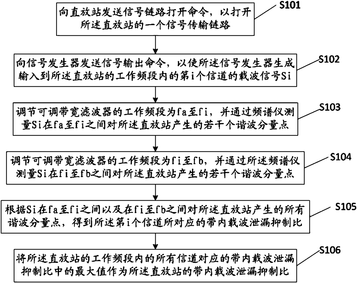
[0032] see figure 1 , which is a schematic flow chart of a repeater in-band carrier leakage suppression test method provided by an embodiment of the present invention, including:

[0033] S101. Send a signal link opening command to the repeater to open a signal transmission link of the repeater; the signal transmission link can be an uplink or a downlink, and only one of them is opened at a time. close the other;

[0034] S102. Send a signal output command to the...


PUM


Abstract

The invention discloses a method and device for testing in-band carrier leakage repression of a repeater. The method comprises the following steps of: sending a signal link opening command to the repeater so as to open one signal transmission link of the repeater; sending a signal output command to a signal generator, so that the signal generator generates a carrier signal Si input into the ith channel in a working frequency band of the repeater; adjusting the working frequency band of an adjustable bandwidth filter from fa to fi, and measuring a plurality of harmonic component points generated by the Si to the repeater between fa and fi through a spectrometer; adjusting the working frequency band of the adjustable bandwidth filter from fi to fb, and measuring a plurality of harmonic component points generated by the Si to the repeater between fi and fb through the spectrometer; and, according to all the harmonic component points, obtaining an in-band carrier leakage repression ratio corresponding to the ith channel and an in-band carrier leakage repression ratio of the repeater. By means of the method and the device disclosed by the invention, the precision of the obtained in-band carrier leakage repression ratio can be effectively improved.

Description

technical field [0001] The invention relates to the field of testing, in particular to a test method and device for in-band carrier leakage suppression of a repeater. Background technique [0002] The in-band and in-band carrier leakage suppression ratio is an important parameter of the repeater. When one of the channels of the repeater has a carrier signal input, it is possible to form several harmonic components on other channels within the working band of the repeater, among which the useful carrier (that is, the channel with carrier signal input) and the maximum power harmonic The ratio of the component values ​​is called the in-band carrier leakage suppression ratio. [0003] When testing the in-band carrier leakage suppression ratio, the input carrier signal will generate some spurious harmonic components to the spectrum analyzer itself, and these spurious harmonic components do not belong to the repeater itself, which leads to the final calculation There is a large ...

Claims


Application Information

Patent Timeline
Patent Type & Authority Patents(China)
IPC IPC(8): H04B17/354H04B17/336H04B17/40
CPCH04B17/336H04B17/354H04B17/40H04B17/402
Inventor 赵栋
Owner GCI SCI & TECH
Why Eureka
Try Eureka