Quantum key distribution system with active monitoring function

A quantum key distribution and function technology, applied in key distribution, can solve problems such as difficult to achieve, strict operating state requirements, inability to defend against multiple attack methods, etc., to achieve the effect of eliminating hidden dangers

Pending Publication Date: 2016-11-16
ZHEJIANG SHENZHOU QUANTUM NETWORK TECH CO LTD
View PDF6 Cites 27 Cited by
  • Summary
  • Abstract
  • Description
  • Claims
  • Application Information

AI Technical Summary

Problems solved by technology

[0009] 1. The ideal model of the QKD system has strict requirements on the operating status of devices and equipment, which is difficult to meet in practice. At present, there are many eavesdropping methods for such vulnerabilities
[0010] 2. The measurement device-independent quantum key distribution p

Method used


Image

  • Quantum key distribution system with active monitoring function
  • Quantum key distribution system with active monitoring function
  • Quantum key distribution system with active monitoring function

Examples


Embodiment 1

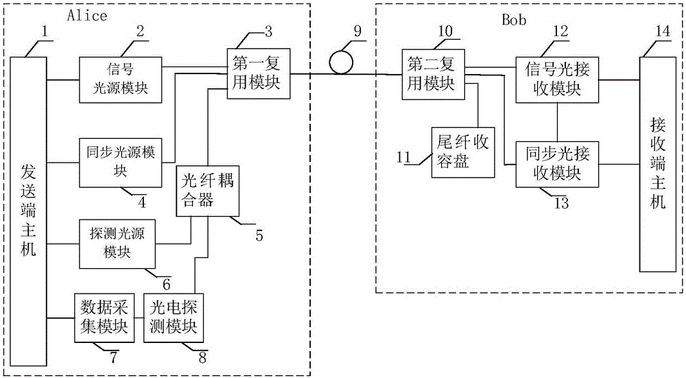
[0050] The QKD system of the present embodiment is as figure 2 As shown, it includes a sending end host 1, a signal light source module 2, a first multiplexing module 3, a synchronous light source module 4, an optical fiber coupler 5, a detection light source module 6, a data acquisition module 7, a photoelectric detection module 8, a channel (ie Fiber channel) 9, second multiplexing module 10, pigtail storage tray 11, signal light receiving module 12, synchronous light receiving module 13, receiving end host 14, each of the modules above can adopt mature prior art.

[0051] For ease of understanding, the above-mentioned modules can be further assigned to the sending end (i.e. Alice end), the receiving end (i.e. Bob end) and the monitoring unit: the sending end and the receiving end connected through a channel (i.e. fiber channel 9), both as quantum The implementer of the key distribution process completes the communication in the quantum key distribution process; the monitor...

Embodiment 2

[0073] In this embodiment, the pulsed light of the synchronous optical module is used as the detection light, see Figure 6 , the QKD system with active monitoring function in this embodiment includes a sending host 1, a signal light source module 2, a first multiplexing module 3, a synchronous light source module 4, an optical fiber coupler 5, a data acquisition module 7, a photoelectric detection module 8, The fiber channel 9, the second multiplexing module 10, the signal light receiving module 12, the synchronous light receiving module 13, the receiving end host 14, the sending end host 1 is connected with the signal light source module 2, the synchronous light source module 4, and the data acquisition module 7 , the signal light source module 2 is connected with the first multiplexing module 3, the data acquisition module 7 is connected with the photoelectric detection module 8, and the synchronous light source module 4 and the photoelectric detection module 8 are connected...


PUM

PropertyMeasurementUnit
Wavelengthaaaaaaaaaa

Abstract

The invention discloses a quantum key distribution system with an active monitoring function. The system comprises a sending end and a receiving end. The sending end and the receiving end are connected through a channel for communication in a quantum key distribution process. The quantum key distribution system also comprises a monitoring unit which is used for monitoring the loss of the channel, thereby monitoring whether there is an eavesdropper in the channel or not. The monitoring unit comprises a detection light generation module, a detection light measurement module and a judgment module. The detection light generation module inputs detection light into the channel. The detection light measurement module is used for measuring intensity values of backward transmission light at various preset sampling points when the detection light is transmitted in the channel. The judgment module is used for judging whether there is eavesdropping in the channel according to the changes of the intensity values. According to the system, through addition of the channel eavesdropping monitoring unit in the general QKD (Quantum Key Distribution) system, a location where the channel light loss is abnormal can be actively discovered, namely the location of the eavesdropper can be discovered rapidly, and the hidden danger can be rapidly eliminated.

Description

technical field [0001] The invention belongs to the technical field of quantum security communication, and in particular relates to a quantum key distribution system with an active monitoring function. Background technique [0002] Quantum key distribution (quantum key distribution, QKD) uses the basic principles of quantum mechanics to ensure the safe sharing of keys between the two parties in communication, which has unconditional security in theory. However, the ideal model of the QKD system has strict requirements on the operating state of the components and equipment, which is difficult to achieve in practice. These defects have caused security loopholes that cannot be ignored in the actual QKD system. Aiming at the security loopholes of QKD system measurement equipment, attack schemes such as strong light blinding attack, detector efficiency mismatch attack, detector dead time attack, and beam splitter wavelength attack have been proposed. [0003] In order to avoid t...

Claims


Application Information

Patent Timeline
IPC IPC(8): H04L9/08H04B10/85
CPCH04B10/85H04L9/0852
Inventor 富尧李浩泉王真真
Owner ZHEJIANG SHENZHOU QUANTUM NETWORK TECH CO LTD
Why Eureka
Try Eureka