Splashing prevention-drying device for high-pressure water jet spray gun
A high-pressure water jet and anti-splash technology, applied in the field of physical cleaning, can solve the problems of no splash, etc., and achieve the effect of changing the working environment, low cost of transformation, and light weight
- Summary
- Abstract
- Description
- Claims
- Application Information
AI Technical Summary
Problems solved by technology
Method used
Image
Examples
Embodiment 1
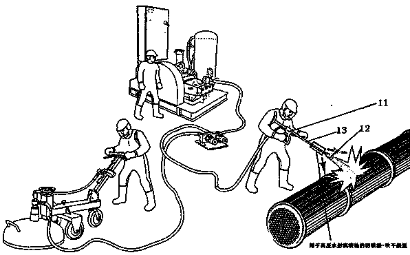
[0036] Such as Figure 1 Shown is a schematic diagram of the high-pressure water jet spray gun in use. The operator holds the high-pressure water jet spray gun against the target to be cleaned, such as Figure 1 Clean the surface of the round tube in it. Pay special attention to the operator's hand-held rectangular block position on the high-pressure water jet spray gun 11 gun barrel, which is the installation position of the anti-splash-drying device disclosed in the present invention. It can be seen that this position is close to the nozzle 12 of the barrel, and the basic structure here is only the barrel 13, so there is no need to modify the structure of the entire gun.
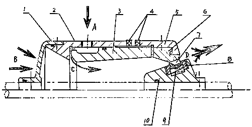
[0037] Below we combine Figure II , to specifically illustrate how the anti-splash-drying device disclosed in the present invention works.
[0038] exist Figure II We can see that the anti-splash-drying device of the high-pressure water jet spray gun includes component one 1, component one includes the...
Embodiment 2
[0043] On the basis of embodiment 1, we further preferred that the transition surface of component one 1 is a screen structure, refer to figure 2 , after the compressed air enters through A, it is continuously ejected from D through C. Therefore, a negative pressure environment is actually formed at C, so the air at B enters the cavity through the filter mesh structure at the same time, and is discharged by D The resulting effect is that it will generate dozens of times (12-40 times) the air intake and ejection volume of the air source.
Embodiment 3
[0045] On the basis of Example 1 and Example 2, we further want to explain that, for different air sources (such as compressed air or regenerative fans), we can configure component-1 (such as closed type) with different structures, and the When the outlet is adjusted to be smaller, the air enters from A and passes through C to be ejected from outlet D, and at the same time, the air near the outlet D is merged and injected together.
PUM
 Abstract
Description
Claims
Application Information
 - R&D
- Intellectual Property
- Life Sciences
- Materials
- Tech Scout
- Unparalleled Data Quality
- Higher Quality Content
- 60% Fewer Hallucinations
Browse by: Latest US Patents, China's latest patents, Technical Efficacy Thesaurus, Application Domain, Technology Topic, Popular Technical Reports.
© 2025 PatSnap. All rights reserved.Legal|Privacy policy|Modern Slavery Act Transparency Statement|Sitemap|About US| Contact US: help@patsnap.com


