A cleaning screen and combine harvester
A technology for cleaning sieves and sieves, applied in the field of cleaning sieves, can solve problems such as easy failure, difficult installation, complex structure, etc., and achieve the effects of high reliability, low cost, and large cleaning volume.
- Summary
- Abstract
- Description
- Claims
- Application Information
AI Technical Summary
Problems solved by technology
Method used
Image
Examples
Embodiment 1
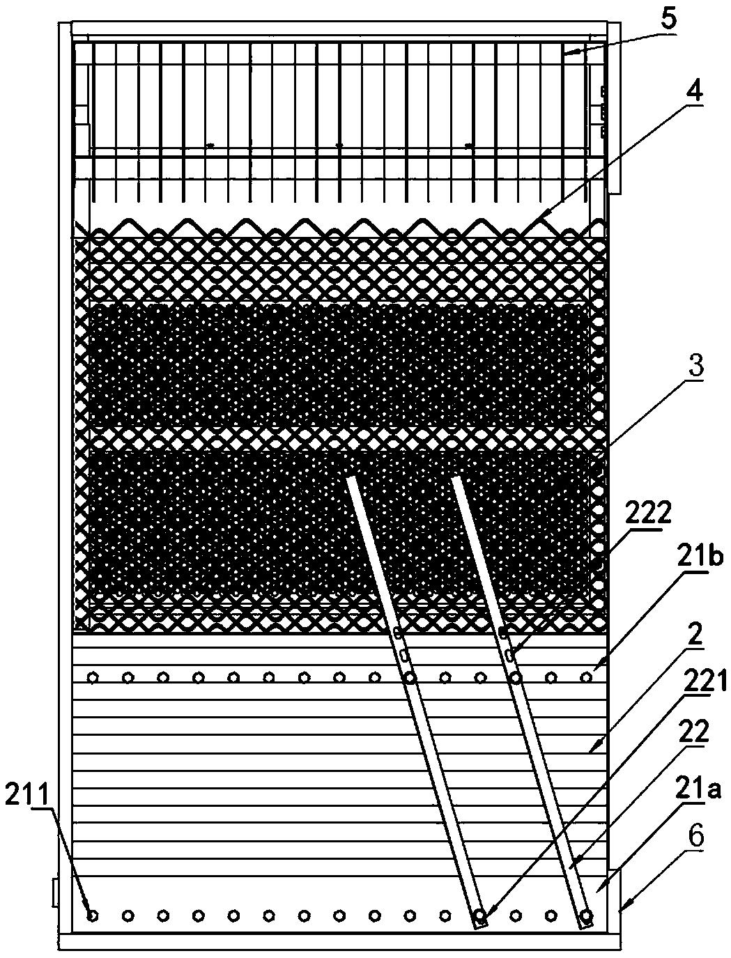
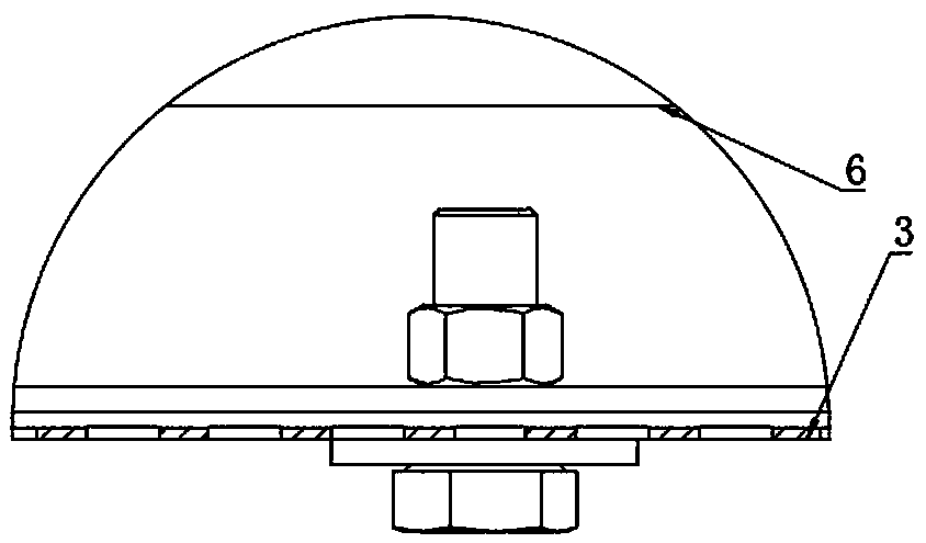
[0042] A combine harvester with features such as figure 1 , 2 A cleaning screen shown in 3 and 3 includes a screen frame 6, a screen piece 4, a draft board 5, a lower screen board 3, and a wave plate 2, and the screen piece 4 is installed between the two side walls of the screen frame 6, The lower sieve plate 3 is located at the bottom of the sieve frame 6 and below the sieve plate 4, the scraping plate 5 is installed between the two side walls of the sieve frame 6, close to the tail of the sieve plate 4, and the wave plate 2 is installed on both sides of the sieve frame 6. between the walls, near the front of the screen 4.
[0043] like Figure 4 , the longitudinal direction of the screen is parallel with a plurality of round steel wires (such as Figure 5 , 2-6mm thick, preferably 4mm) made of screen bar 41, the screen bar has a bent portion 411, the bent portion is provided with a corner 4111, the length direction of the screen bar 41 is provided with a first bent portio...
Embodiment 2
[0048] A combine harvester with features such as figure 1 , 2 A cleaning screen shown in 3 and 3 includes a screen frame 6, a screen piece 4, a draft board 5, a lower screen board 3, and a wave plate 2, and the screen piece 4 is installed between the two side walls of the screen frame 6, The lower sieve plate 3 is located at the bottom of the sieve frame 6 and below the sieve plate 4, the scraping plate 5 is installed between the two side walls of the sieve frame 6, close to the tail of the sieve plate 4, and the wave plate 2 is installed on both sides of the sieve frame 6. between the walls, near the front of the screen 4.
[0049] like Figure 4 , the longitudinal direction of the sieve piece is provided with a plurality of sieve bars 41 made of metal wire-shaped materials with a diameter of 2-6mm in the outer circle of the cross-section (such as square steel wires with a side length of 4mm). There are folded corners 4111 , the first folded portion 411a and the second fol...
Embodiment 3
[0054] A combine harvester with features such as figure 1 , 2 A cleaning screen shown in 3 and 3 includes a screen frame 6, a screen piece 4, a draft board 5, a lower screen board 3, and a wave plate 2, and the screen piece 4 is installed between the two side walls of the screen frame 6, The lower sieve plate 3 is located at the bottom of the sieve frame 6 and below the sieve plate 4, the scraping plate 5 is installed between the two side walls of the sieve frame 6, close to the tail of the sieve plate 4, and the wave plate 2 is installed on both sides of the sieve frame 6. between the walls, near the front of the screen 4.
[0055] like Figure 4 , the screen is formed by stamping and bending of steel plate. Specifically, it includes a screen bar 41 arranged in parallel in the longitudinal direction. The screen bar has a bent portion 411. The opening directions of the corners of the bent portion 411a and the second bent portion 411b are opposite to each other. like Fig...
PUM
 Abstract
Description
Claims
Application Information
 - R&D
- Intellectual Property
- Life Sciences
- Materials
- Tech Scout
- Unparalleled Data Quality
- Higher Quality Content
- 60% Fewer Hallucinations
Browse by: Latest US Patents, China's latest patents, Technical Efficacy Thesaurus, Application Domain, Technology Topic, Popular Technical Reports.
© 2025 PatSnap. All rights reserved.Legal|Privacy policy|Modern Slavery Act Transparency Statement|Sitemap|About US| Contact US: help@patsnap.com


