A method and device for in situ drug injection

An injection and in-situ technology, applied in the restoration of polluted soil, etc., can solve the problems of low injection efficiency, easy to be blocked, and troublesome process, and achieve the effect of large passing area, not easy to block, and easy to operate.

Active Publication Date: 2018-10-02
浙江博世华环保科技有限公司
View PDF12 Cites 0 Cited by
  • Summary
  • Abstract
  • Description
  • Claims
  • Application Information

AI Technical Summary

Problems solved by technology

In this technical solution, it is necessary to drill the drug well first, and then inject the drug. While the process is relatively cumbersome, the hole for the existing drill bit to output the drug is small, easy to be blocked, and the injection efficiency is low.

Method used


Image

  • A method and device for in situ drug injection
  • A method and device for in situ drug injection
  • A method and device for in situ drug injection

Examples


Embodiment 1

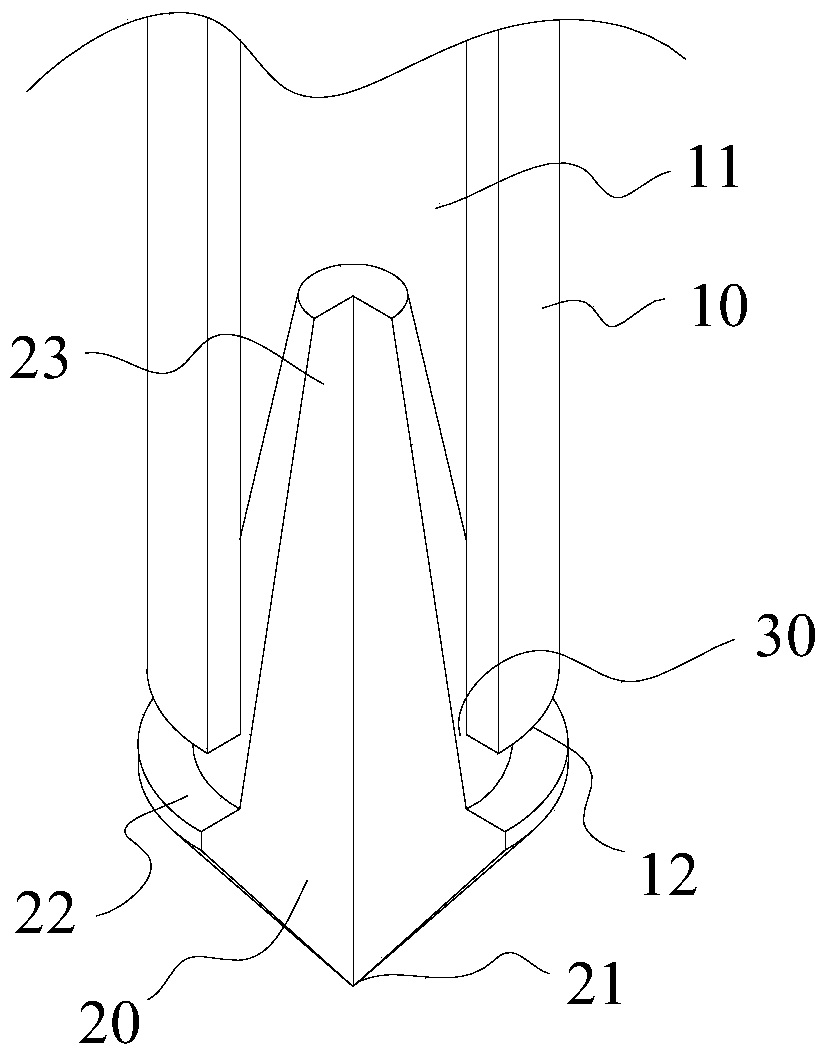
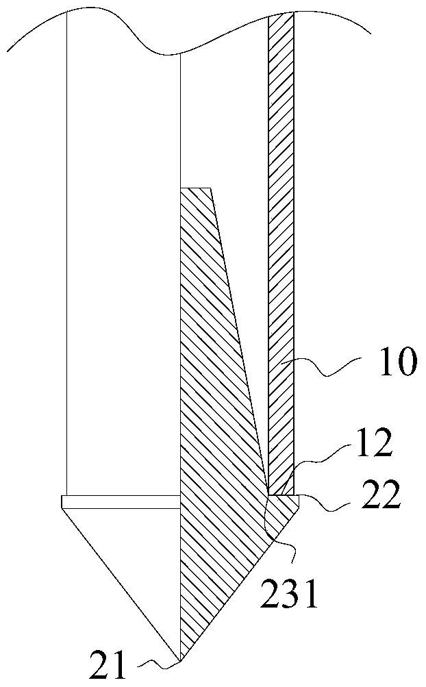
[0040] Such as figure 1 As shown, a method for in-situ drug injection includes a drill pipe 10 and a drill bit 20, the drill bit 20 includes a working section 21 in contact with the ground, a tail section 23 inserted into the inside of the drill pipe 11, and a tail section 23 between the working section 21 and the tail section. 23 is used to support the working platform 22 of the pressure of the drill pipe 10; the drill pipe 10 has a feed state in which the bottom surface of the drill pipe 12 is offset against the work platform 22 and a drug injection state separated from the bottom surface of the drill pipe 12 and the work platform 22. In the drug injection state, the gap 30 between the drill pipe 10 and the drill bit 20 is a drug delivery channel.

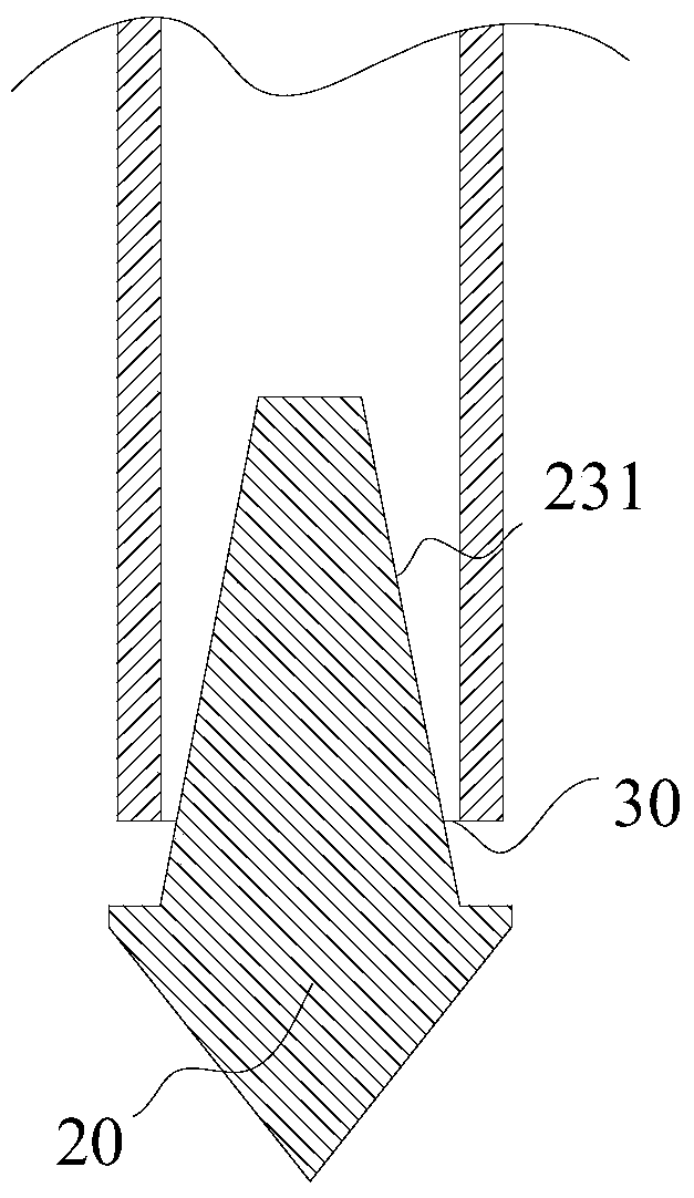
[0041] Such as figure 2 As shown, the working section of the drill bit 20 is in the shape of a cone whose outer diameter gradually decreases along the direction away from the drill pipe, so as to facilitate overcoming the surfa...

Embodiment 2

[0047] Such as Figure 4 As shown, a method for in-situ drug injection includes a drill pipe and a drill bit, the drill bit includes a working section in contact with the ground, a tail section inserted into the inside of the drill pipe, and is used to support the drill between the working section and the tail section The working platform of pipe pressure; the drill pipe has the feeding state where the bottom surface of the drill pipe is offset against the working platform, and the injection state where the bottom surface of the drill pipe is separated from the working platform. In this injection state, the gap between the drill pipe and the drill bit is the drug delivery channel. The working section of the drill bit has a tapered outer diameter gradually decreasing along the direction away from the drill pipe, which is convenient for overcoming the surface resistance. The tail section is movably inserted into the drill pipe, and the outer diameter of the tail section graduall...


PUM


Abstract

The invention discloses an in-situ chemical injection method. The in-situ chemical injection method comprises: feeding a drill bit to a specified depth through a drill pipe, lifting the drill pipe to be separated from the drill bit to form a chemical supply channel, and injecting a chemical into a specified position via the chemical supply channel. Meanwhile, the present invention discloses a device for implementing the method; the device comprises a drill pipe and a drill bit; the drill bit comprises a working section in contact with ground, a tail section inserted into the drill bit, and a working platform located between the working section and the tail section and used for bearing the pressure of the drill pipe; the drill pipe has a feed state of propping against the working platform and a chemical injection state of being separated from the drill bit; in the chemical injection state, a gap between the drill pipe and the drill bit forms a chemical supply channel. The in-situ chemical injection device is provided with the annular and adjustable chemical supply channel that is large in passing area and not prone to blockage; due to the design of a detachable retainer ring and an extension sleeve, the in-situ chemical injection device is applicable to different working environments and wide in application range; further, due to the design of integrated well drilling and chemical supply actions, convenient operations can be realized.

Description

technical field [0001] The invention relates to the field of environmental protection, in particular to a method and device for in-situ drug injection. Background technique [0002] With the implementation of national policies such as "retreating from two to three", "retreating from cities and entering parks", and "industrial transfer", almost all large and medium-sized cities in the country are facing the problem of closing and relocating a large number of enterprises in heavily polluting industries, resulting in a large number of cities Abandoned and abandoned sites, if a considerable number of sites are directly developed without restoration, will lead to a large number of environmental problems. The national soil pollution survey data released by the Ministry of Environmental Protection shows that the overall soil environment in the country is not optimistic. Some areas have serious soil pollution. In order to completely solve such problems, the state and relevant minis...

Claims


Application Information

Patent Timeline
Patent Type & Authority Patents(China)
IPC IPC(8): B09C1/08
CPCB09C1/08B09C2101/00
Inventor 陈昆柏温俊明金祥福况武段德超马嘉伟高全喜张明赵怡阳金旭平
Owner 浙江博世华环保科技有限公司
Why Eureka
Try Eureka