

Liquid Bubble Monitoring Equipment
A technology for monitoring equipment and liquid bubbles, which can be used in blood circulation processing, medical devices, and other medical devices. Monitor the effect of the effect
Inactive Publication Date: 2018-05-11
重庆青年职业技术学院
View PDF7 Cites 0 Cited by
- Summary
- Abstract
- Description
- Claims
- Application Information
AI Technical Summary
Problems solved by technology
[0006] Aiming at the problem that the existing liquid bubble monitoring equipment cannot monitor the blood (which can be mixed with physiological saline) in the input pipeline and is likely to cause false alarms, it provides a reliable and reliable method for monitoring the blood before it finally enters the human body. High liquid bubble monitoring equipment
Method used
View moreImage
Smart ImageViewing Examples

Examples
Embodiment 1
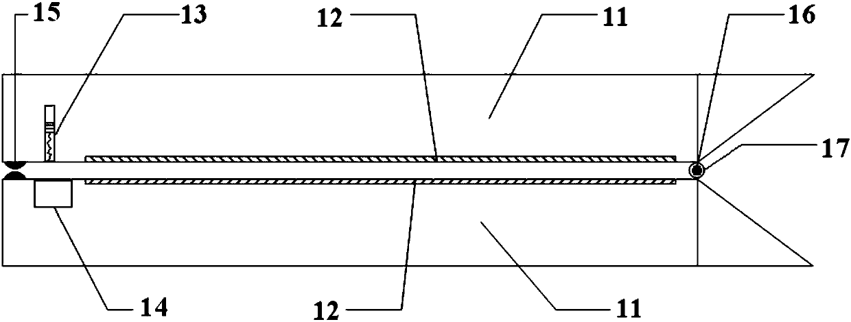
[0033] Such as Figure 2 to Figure 9 As shown, the present embodiment provides a liquid bubble monitoring device 1, which includes:
[0034] A clamping unit, which includes two rotatably connected clamping parts 11 for clamping the end of the input pipeline 82 of the blood purification device 8;
[0035] Two capacitive pole pieces 12 are respectively arranged at opposite positions inside the two clamping parts 11;
Login to View More PUM
 Abstract
The invention provides liquid bubble monitor equipment, belongs to the technical field of blood purification, and aims to solve the problem that existing liquid bubble monitor equipment cannot monitor normal saline-mixed blood or pure blood in an input pipeline and can easily causes false information. The liquid bubble monitor equipment comprises a clamping unit, two capacitance polar plates and a detection circuit unit, wherein the clamping unit comprises two clamping parts which are connected in a rotating manner for clamping the tail ends of the input pipeline of blood purification equipment; the two capacitance polar plates are respectively arranged on opposite positions inside the two clamping parts; and the detection circuit unit is connected with the capacitance polar plates, and is used for determining whether bubbles exist in the input pipeline or not according to the capacitance value between the two capacitance polar plates.
Description
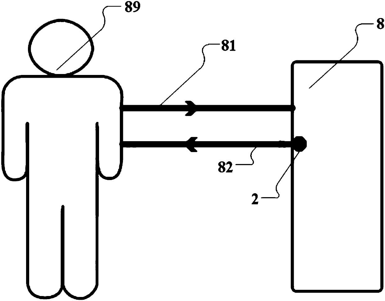
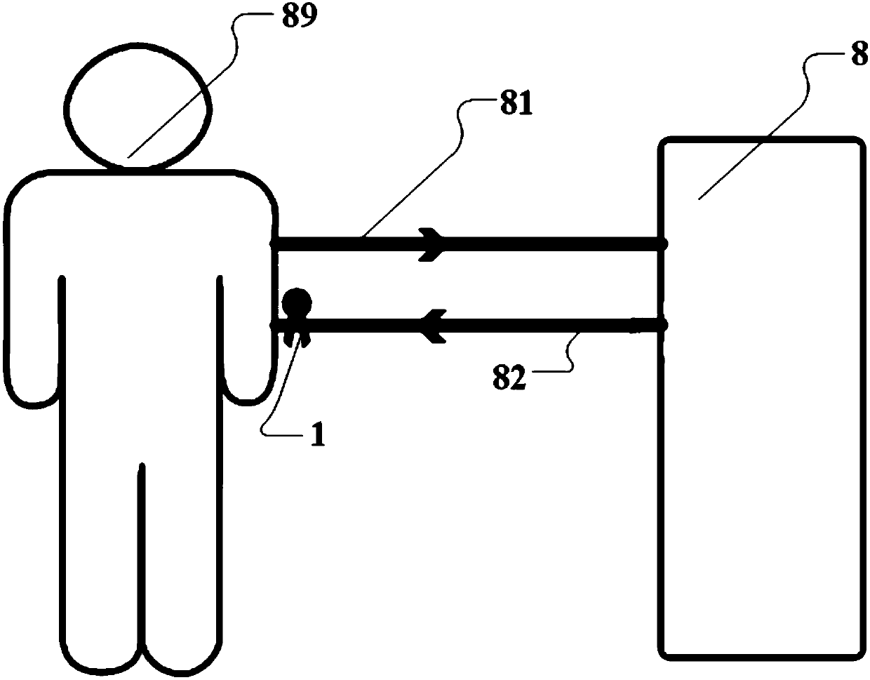
technical field [0001] The invention belongs to the technical field of blood purification, and in particular relates to a liquid bubble monitoring device. Background technique [0002] In the treatment of renal failure, drug poisoning, etc., blood purification technology can be used. blood purification process such as figure 1 As shown, the blood is transmitted from the human body 89 to the purification device 8 through the output pipeline 81, and is purified in the purification device 8, and the purified blood (which may be mixed with physiological saline) is then returned to the human body 89 through the input pipeline 82 . Since it is very dangerous to enter the blood vessels, it is necessary to monitor whether there are air bubbles in the blood and the injected saline during the blood purification process. The existing liquid bubble monitoring device 2 is an ultrasonic bubble monitor, which is located at the beginning of the corresponding input pipeline 82 in the puri...
Claims
Login to View More Application Information
Patent Timeline
 Patent Type & AuthorityPatents(China)
IPC IPC(8): A61M1/36
CPCA61M1/3626A61M2205/18A61M2205/3317
Inventor卢继珍
Owner重庆青年职业技术学院