Sump oil vibration filter apparatus with residual oil filter
A vibration filtration and residual oil technology, applied in the direction of mobile filter element filter, filtration separation, membrane filter, etc., can solve the problems of slow filtration speed, dirty oil vibration filter can not filter, easy to block, etc., to improve the use effect Effect
- Summary
- Abstract
- Description
- Claims
- Application Information
AI Technical Summary
Problems solved by technology
Method used
Image

Examples
Embodiment 1
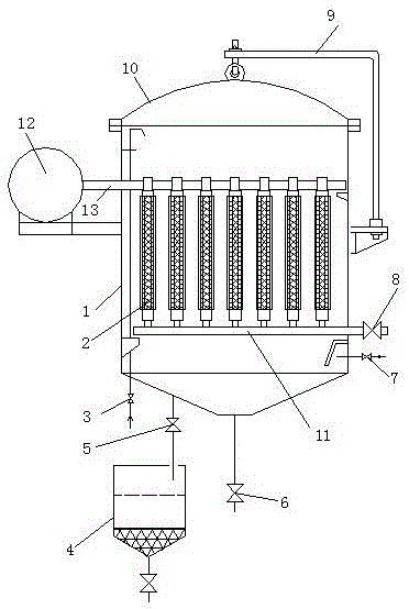
[0013] refer to figure 1 , a dirty oil vibrating filter device provided with residual oil filtration, the tank body 1 and the tank body cover 10 are connected by flanges to form a sealed tank, a vibrating filter core plate 2 is longitudinally arranged in the tank body 1, and the vibrating filter core plate The bottom of 2 is connected with an oil outlet pipe 11, one end of the oil outlet pipe 11 extends out of the tank body 1 and is provided with an oil outlet valve 8, the top of the vibrating filter core plate 2 is connected with a vibrating shaft 13, and the bottom of the tank body 1 is provided with Intake pipe and compressed air valve 3, oil inlet pipe and oil inlet valve 7 are arranged at the bottom of tank body 1, drain pipe and drain valve 6 are arranged at the bottom of tank body 1, vibration shaft 6 and vibration pump outside tank body 1 12 connections, the bottom of the tank body 1 is provided with a residual oil discharge pipe and a residual oil discharge valve 5, a...
Embodiment 2
[0015] refer to figure 1 , a dirty oil vibrating filter device provided with residual oil filtration, the tank body 1 and the tank body cover 10 are flange-connected to form a sealed tank, a vibrating filter core plate 2 is longitudinally arranged in the tank body 1, and the vibrating filter core plate The bottom of 2 is connected with an oil outlet pipe 11, one end of the oil outlet pipe 11 extends out of the tank body 1 and is provided with an oil outlet valve 8, the top of the vibrating filter core plate 2 is connected with a vibrating shaft 13, and the bottom of the tank body 1 is provided with Intake pipe and compressed air valve 3, oil inlet pipe and oil inlet valve 7 are arranged at the bottom of tank body 1, drain pipe and drain valve 6 are arranged at the bottom of tank body 1, vibration shaft 6 and vibration pump outside tank body 1 12 connections, the bottom of the tank body 1 is provided with a residual oil discharge pipe and a residual oil valve 5, and the residua...
Embodiment 3
[0018] refer to figure 1 , a dirty oil vibrating filter device provided with residual oil filtration, the tank body 1 and the tank body cover 10 are flange-connected to form a sealed tank, a vibrating filter core plate 2 is longitudinally arranged in the tank body 1, and the vibrating filter core plate The bottom of 2 is connected with an oil outlet pipe 11, one end of the oil outlet pipe 11 extends out of the tank body 1 and is provided with an oil outlet valve 8, the top of the vibrating filter core plate 2 is connected with a vibrating shaft 13, and the bottom of the tank body 1 is provided with Intake pipe and compressed air valve 3, oil inlet pipe and oil inlet valve 7 are arranged at the bottom of tank body 1, drain pipe and drain valve 6 are arranged at the bottom of tank body 1, vibration shaft 6 and vibration pump outside tank body 1 12 connections, the bottom of the tank body 1 is provided with a residual oil discharge pipe and a residual oil valve 5, and the residua...
PUM
 Abstract
Description
Claims
Application Information
PatSnap Eureka turns technology decisions into work you can execute. Powered by our Innovation Knowledge Graph, it runs expert workflows across engineering, life sciences, materials and intellectual property. Get your review-ready output in minutes.


