
Bicycle and electric power assisting device thereof

An electric power assist and bicycle technology, applied in vehicle parts, rider drive, transportation and packaging, etc., can solve the problem of difficult installation and achieve the effect of convenient installation

Inactive Publication Date: 2016-11-23
HONG FU JIN PRECISION IND (SHENZHEN) CO LTD +1
View PDF5 Cites 7 Cited by
  • Summary
  • Abstract
  • Description
  • Claims
  • Application Information

AI Technical Summary

Problems solved by technology

However, when installing the hub motor, the bicycle usually needs to be disassembled, and even the structure of the bicycle needs to be changed to match the installation, which is difficult to install

Method used


Image

  • Bicycle and electric power assisting device thereof
  • Bicycle and electric power assisting device thereof

Examples


Embodiment Construction

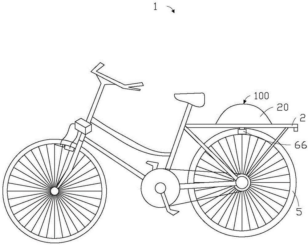
[0043] see figure 1 , the embodiment of the present invention provides a bicycle 1 , which includes a frame 2 , a rear wheel 5 arranged on the frame 2 , and an electric power assist device 100 . In this embodiment, the electric power assist device 100 is arranged adjacent to the rear wheel 5 and is connected to the rear wheel 5 to drive the rear wheel 5 to rotate and thus drive the bicycle 1 to walk. It can be understood that the bicycle 1 may also include structures (not shown) such as front wheels, pedals, and cranks, which will not be introduced here for the sake of omitting space.

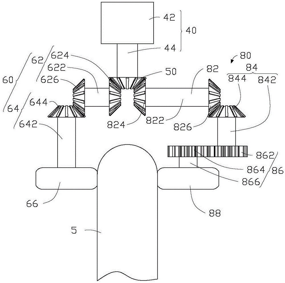
[0044] Please also see figure 2 , the electric power booster 100 includes a housing 20 , a driving member 40 , a main gear 50 , a first transmission assembly 60 , a second transmission assembly 80 , a first friction wheel 66 and a second friction wheel 88 . The housing 20 is connected to the frame 2 and is disposed adjacent to the rear wheel 5 . The driving element 40 , the main gear 50 , t...


PUM


Abstract

An electric power assisting device comprises a drive piece, a main gear, transmission assemblies and friction wheels. The main gear is connected with the drive piece and can rotate in the first direction. The transmission assemblies comprise a first transmission gear and a second transmission gear. The first transmission gear comprises a transmission shaft, a first tapered tooth part and a second tapered tooth part, wherein the transmission shaft is sleeved with the first tapered tooth part and the second tapered tooth part in a spaced manner and extends in the second direction perpendicular to the first direction. The first tapered tooth part is engaged with the main gear. The second transmission gear comprises a rotary shaft and a third tapered tooth part arranged on the rotary shaft in a sleeving manner. The rotary shat extends in the first direction. The third tapered tooth part is engaged with the second tapered tooth part. The friction wheels are connected with the rotary shaft, spaced from the third tapered tooth part and used for abutting against a tire of a bicycle. The electric power assisting device is convenient to install.

Description

technical field [0001] The invention relates to an electric booster installed on a bicycle. Background technique [0002] Its electric booster of bicycle of prior art usually adopts wheel hub motor. However, when the hub motor is installed, the bicycle usually needs to be disassembled, and even the structure of the bicycle needs to be changed to match the installation, so the installation is relatively difficult. Contents of the invention [0003] In view of the above, it is necessary to provide an electric power booster that is easy to install. [0004] The invention also provides a bicycle using the electric power assist device. [0005] An electric power booster, which includes a driving member, a main gear, a first transmission assembly and a first friction wheel, the main gear is connected to the driving member and can rotate around a first direction, and the first transmission assembly includes sequentially connected first A transmission gear and a second transmis...

Claims


Application Information

Patent Timeline
Patent Type & Authority Applications(China)
IPC IPC(8): B62M6/75
CPCB62M6/75
Inventor 陈彦吉施昌沅许仕欣
Owner HONG FU JIN PRECISION IND (SHENZHEN) CO LTD
Learn More