An automatic feeding device for an automatic capping machine for electronic connectors

An electronic connector, automatic feeding technology, applied to vibrating conveyors, conveyors, conveyor objects, etc., can solve the problems of manual installation of end caps, waste of resources, high labor intensity, and achieve smooth and accurate feeding. , the effect of improving efficiency and reducing costs

Active Publication Date: 2018-06-19
SUZHOU JUNCHANG COMM TECH CO LTD
View PDF9 Cites 0 Cited by
  • Summary
  • Abstract
  • Description
  • Claims
  • Application Information

AI Technical Summary

Problems solved by technology

However, there is no automatic capping equipment for electronic connectors at present. The end caps are placed on both ends of the electronic connectors through a large number of manual operations. The labor intensity is high, the labor cost is high, and it is difficult to control the insertion of the end caps. quality
In addition, manual installation of end caps may be missing due to manual negligence, which affects the pass rate of products and causes a waste of resources
However, on the automatic capping machine for electronic connectors, the problem of automatic feeding of the connectors needs to be solved at first, but there is no automatic feeding device for electronic connectors at present.

Method used


Image

  • An automatic feeding device for an automatic capping machine for electronic connectors
  • An automatic feeding device for an automatic capping machine for electronic connectors
  • An automatic feeding device for an automatic capping machine for electronic connectors

Examples


Embodiment Construction

[0022] The present invention will be described in further detail below through specific examples.

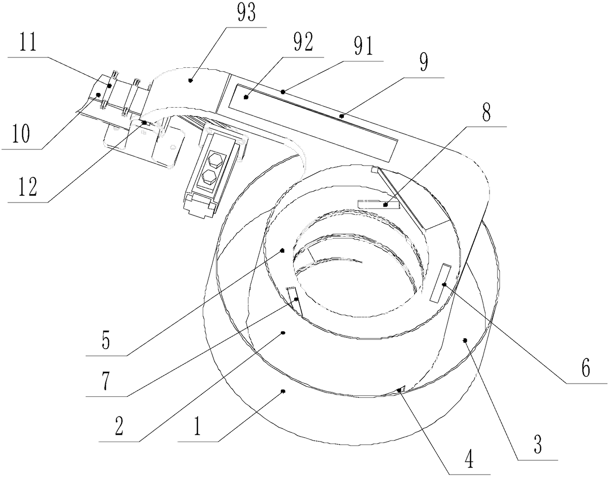
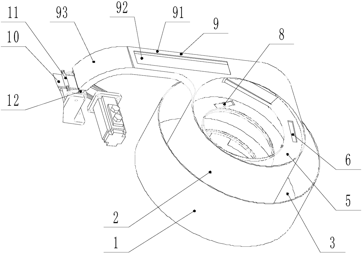
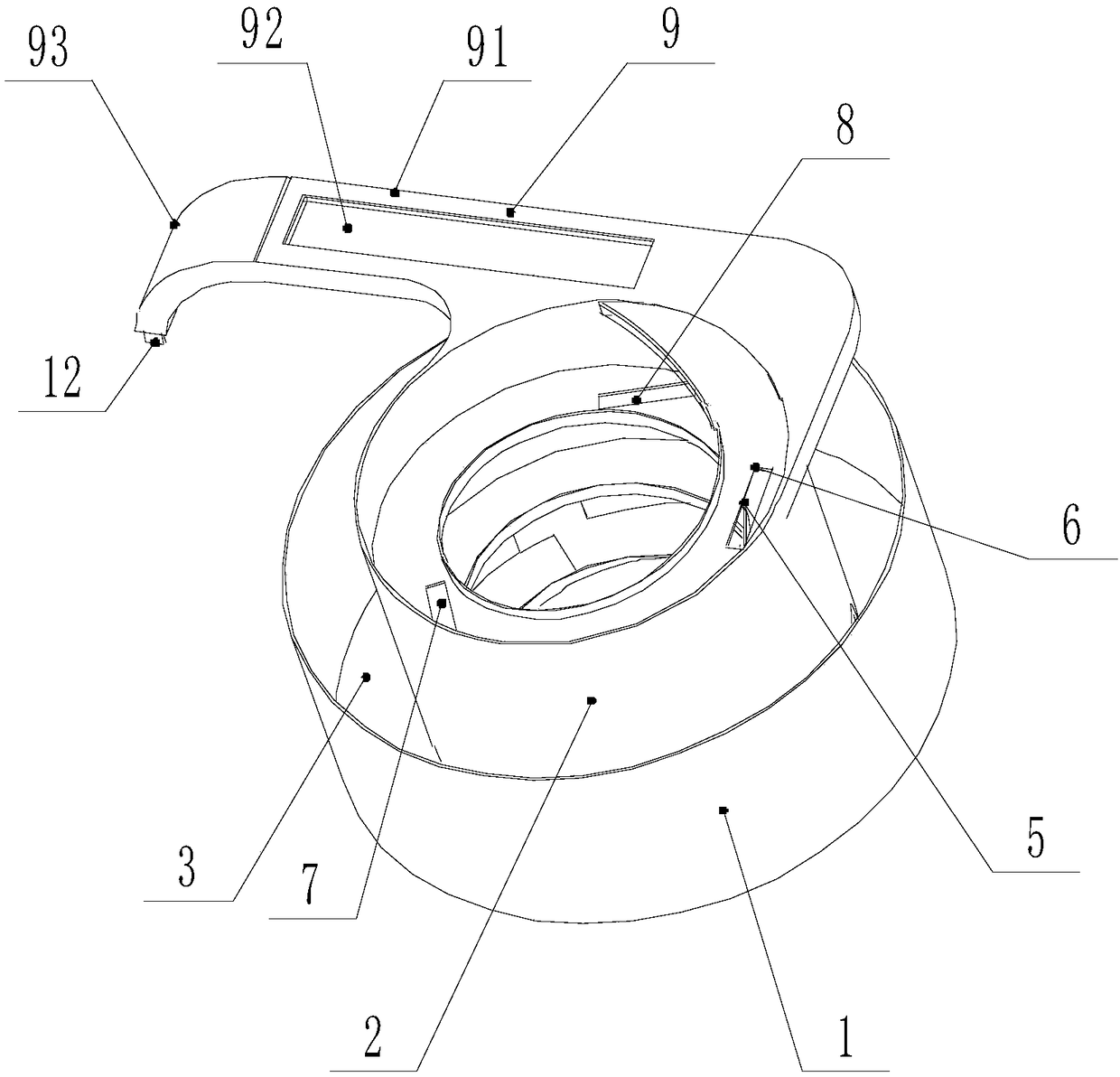
[0023] The connector mentioned in this embodiment is actually the same part as the electronic connector 11, and both ends of the connector need to be covered with end caps during heat treatment. The upstream end and downstream end mentioned in this embodiment are determined according to the conveying direction of the electronic connector 11 , the position passing first is upstream, and the position passing later is downstream.

[0024] Such as Figure 1 to Figure 4 As shown, an automatic feeding device for an automatic capping machine for electronic connectors 11 includes a vibrating plate and a connecting channel 9 for connectors. The vibrating plate includes an outer disc body 1 and an inner disc body 2 arranged concentrically. The outer disc body 1 A material storage space 3 is formed between the inner disc body 2, and the bottom of the inner disc body 2 is provided with a c...


PUM


Abstract

The invention discloses an automatic feeding device of an automatic capping machine for electronic connectors. The automatic feeding device comprises a vibration plate and a connector connecting channel. The vibration plate comprises an outer plate body and an inner plate body. A connector conveying rail is arranged on the inner wall of the inner plate body, and the lower end of the connector conveying rail is tangent to a plate main body of the inner plate body. A removing structure is arranged on the connector conveying rail. The upstream end of the connector connecting channel is in smooth connection with the upper end of the connector conveying rail, and the downstream end of the connector connecting channel extends downwards to the position above a conveyor belt of the automatic capping machine. A plurality of feeding clamp grooves are formed in the conveyor belt, and limiting mechanisms are arranged at the position, on the two sides of the conveyor belt, of the downstream end of the connector connecting channel. The automatic feeding device can achieve automatic arraying and feeding of connectors, the electronic connectors automatically fall into the feeding clamp grooves of the conveyor belt, and automatic capping can be achieved conveniently.

Description

technical field [0001] The invention relates to an automatic feeding device, in particular to an automatic feeding device for an automatic capping machine for electronic connectors. Background technique [0002] Electronic connectors need to be heat treated during the manufacturing process, and the end of the electronic connector has several axial groove structures. Therefore, in order to reduce the deformation of the end of the electronic connector during heat treatment, it is necessary to The two ends of the connector are equipped with an end cap to limit the deformation of the end, so that the specifications of the electronic connector after heat treatment meet the requirements, and the qualified rate of the product is higher. However, there is no automatic capping equipment for electronic connectors at present. The end caps are placed on both ends of the electronic connectors through a large number of manual operations. The labor intensity is high, the labor cost is high...

Claims


Application Information

Patent Timeline
Patent Type & Authority Patents(China)
IPC IPC(8): B65G47/28B65G47/256B65G27/02
CPCB65G27/02B65G47/256B65G47/28
Inventor 丁耀琴周加茹何丽敏
Owner SUZHOU JUNCHANG COMM TECH CO LTD
Why Eureka
Try Eureka