Pushing mechanism in feeding device

A technology of a feeding device and a pushing mechanism, which is applied in the field of feeding devices and pushing mechanisms, can solve the problems that the feeding cannot be smoothly pushed, the workpiece is easy to move, etc., and achieves good positioning effect, smooth and accurate feeding, and easy control. The effect of reciprocating motion

Active Publication Date: 2017-06-16
JINING XINRUIDA INFORMATION TECH CO LTD
View PDF1 Cites 0 Cited by
  • Summary
  • Abstract
  • Description
  • Claims
  • Application Information

AI Technical Summary

Problems solved by technology

However, the feeding device is pushing the workpiece (such as Image 6 During the shown workpiece 12), since the middle part of an end surface of the workpiece has a protrusion protruding from the end surface, the workpiece is prone to move when pushing, so that the feeding cannot be pushed smoothly.

Method used


Image

  • Pushing mechanism in feeding device
  • Pushing mechanism in feeding device
  • Pushing mechanism in feeding device

Examples


Embodiment 1

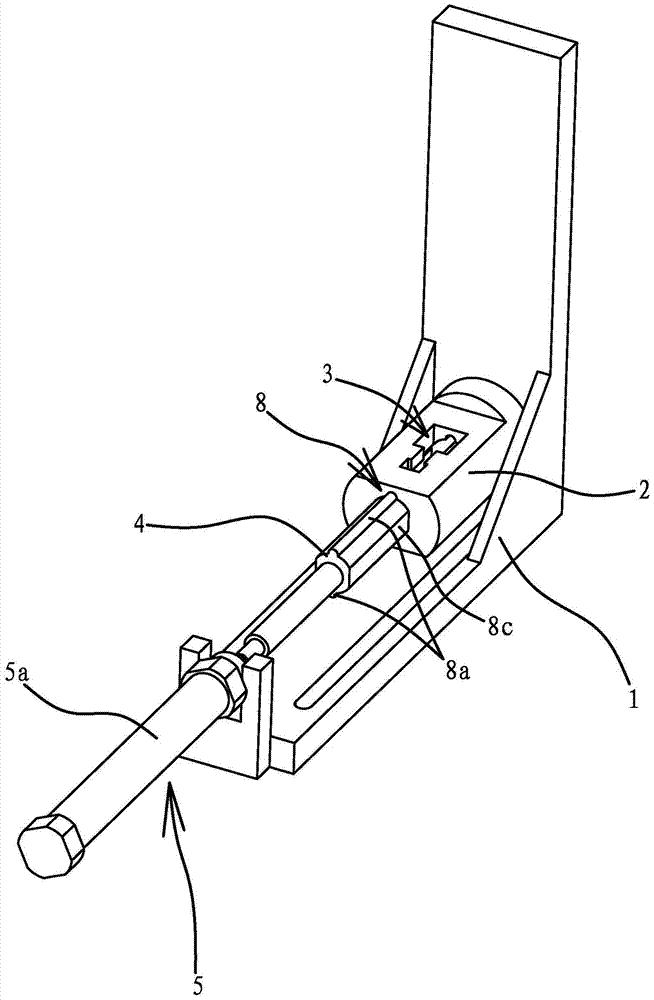
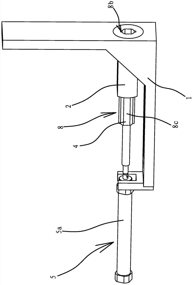
[0035] Such as Figure 1 to 4 7. As shown in 7, the pushing mechanism in the feeding device includes a bracket 1 and a feeding barrel 2 arranged on the bracket 1. One side of the feeding barrel 2 is provided with a feeding port 3, a feeding port 3 and a feeding barrel 2. The cavities are connected, the feeding barrel 2 is provided with a push rod 4, and the support 1 is also provided with a drive mechanism 5 that can drive the push rod 4 to reciprocate. The drive mechanism 5 is a cylinder fixedly connected to the support 1. The piston rod of the cylinder 5a is fixedly connected with the push rod 4.

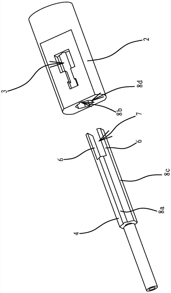
[0036] The inner end surface of the push rod 4 has a cylindrical pusher 6 protruding from its end surface. The number of the pusher 6 is two, and there is a gap 7 between the two pushers 6, and the cylinder 5a can Drive the push rod 4 to translate so that the clearance gap 7 can be directly opposite to the feed opening 3 of the feeding barrel 2. The pushing part 6 and the pushing r...

Embodiment 2

[0045] The structure and principle of this embodiment are basically the same as those of the first embodiment, and the difference lies in: Figure 5 with 6 As shown, a strip-shaped guide 11 is fixedly connected to the upper side of the feeding barrel 2, and the guide 11 is arranged perpendicular to the axis of the feeding barrel 2. The upper side of the guide 11 has a guide groove 11a, which is arranged along the axial direction of the guide 11, and the bottom of the guide groove 11a is provided with a through feeding port 11b. The feeding port 11b is connected to the feeding barrel 2. The structure and position of the feed port 1-3 correspond one by one. A blanking plate 9 is embedded in the guide groove 11a, and a driving mechanism 10 that can drive the blanking plate 9 to reciprocate is positioned on the feeding barrel 2. The blanking plate 9 is provided with two feeding ports 9a and two feeding ports 9a. Vertically penetrating through the blanking plate 9, the second drivin...


PUM


Abstract

The invention provides a pushing mechanism of a feeding device, belongs to the technical field of machine components, and solves the problem of incapability of pushing smoothly of the existing feeding device. The pushing mechanism of the feeding device comprises a support and a feeding tube arranged on the support, wherein one side of the feeding tube is provided with a feed port I which is communicated with a cavity of the feeding tube; a pushing rod is arranged in the feeding tube; the support is further provided with a driving mechanism I capable of driving the pushing rod to do reciprocating movements; a pushing part which is protruded out of the end face of the pushing rod and is in a shape of a column is arranged on the inner end face of the pushing rod. The pushing mechanism of the feeding device has the advantages of reliable operation and smooth feeding of workpieces.

Description

Technical field [0001] The invention belongs to the technical field of machine tool components, and relates to a feeding device, in particular to a pushing mechanism in the feeding device. Background technique [0002] Machine tools are commonly used equipment for metal processing. At present, all machine tools are manually operated. Manually carry out the processing procedures of workpiece loading, clamping, cutting, loosening, and blanking. Its efficiency is low and the technical requirements for workers are high. Non-technical personnel cannot operate. Because a machine tool needs to be controlled by one person, a large number of technicians are required to cause high labor costs for business operations, high labor intensity under long-term work, and fatigue of workers, resulting in unstable product accuracy. [0003] For this situation, people have realized this shortcoming and have made improvements, such as a feeding device for an automatic processing machine tool for special...

Claims


Application Information

Patent Timeline
Patent Type & Authority Patents(China)
IPC IPC(8): B23Q7/06
CPCB23Q7/06
Inventor 杨建龙
Owner JINING XINRUIDA INFORMATION TECH CO LTD
Why Eureka
Try Eureka