Pusher components in the feeder

A feeding device and component technology, which is applied in metal processing and other directions, can solve the problems of easy falling of workpieces and processing omissions, etc., and achieve good positioning effect, smooth and accurate feeding, and good guiding effect

Active Publication Date: 2016-05-25
JINING XINRUIDA INFORMATION TECH CO LTD
View PDF7 Cites 0 Cited by
  • Summary
  • Abstract
  • Description
  • Claims
  • Application Information

AI Technical Summary

Problems solved by technology

When pushing the workpiece, the cylinder pushes the workpiece into the fixture, but when the position of the workpiece deviates, when the cylinder pushes the workpiece to the fixture, the workpiece that does not enter the fixture smoothly will fall when the piston rod of the cylinder retracts. omission of processing

Method used


Image

  • Pusher components in the feeder
  • Pusher components in the feeder
  • Pusher components in the feeder

Examples


Embodiment 1

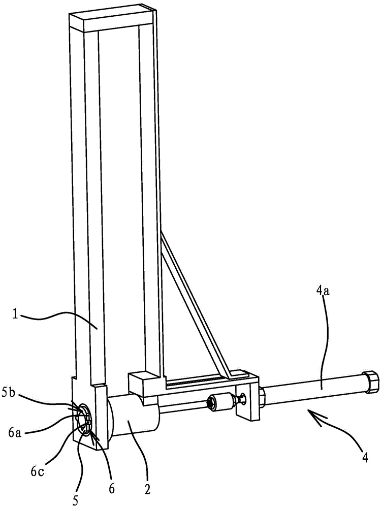
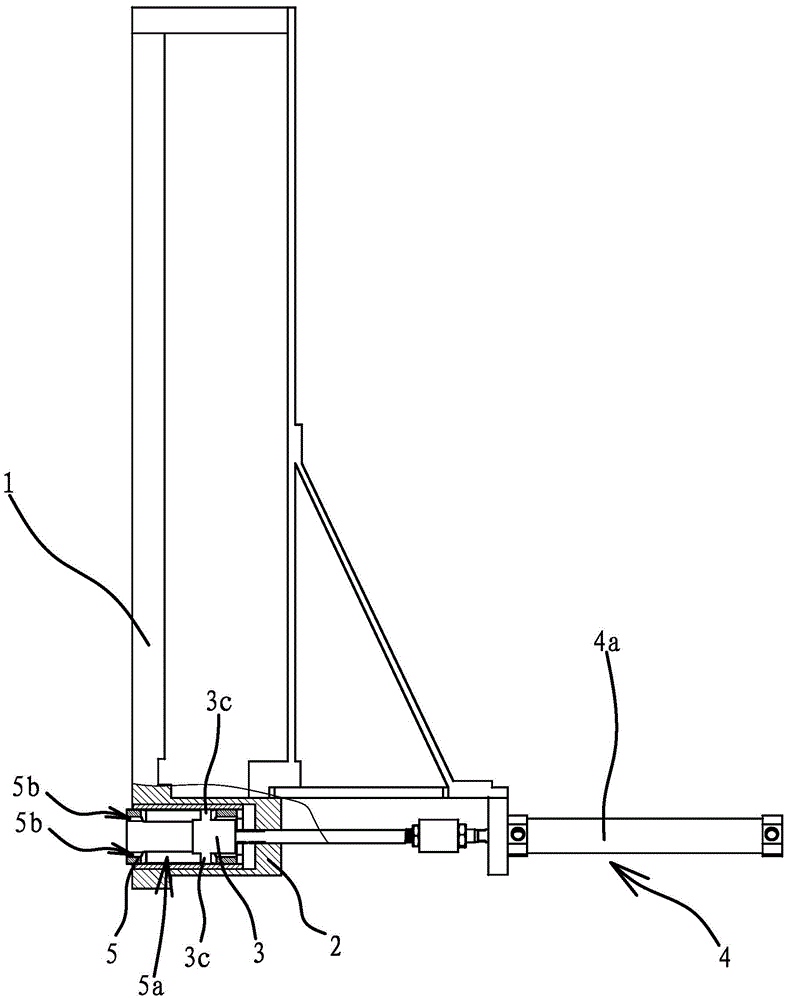
[0030] like Figures 1 to 3 As shown, the pusher assembly in the feeding device includes a bracket 1 and a feeding cylinder 2 arranged on the bracket 1. The bracket 1 is in the shape of a frame, which has the advantages of firm structure and convenient manufacture. The feeding cylinder 2 is installed on the underside of the support 1 . The feeding cylinder 2 is provided with a push rod 3, and the bracket 1 is also provided with a drive mechanism 4, and the drive mechanism 4 drives the push rod 3 to reciprocate in translation, and the drive mechanism 4 includes a cylinder body fixedly connected to the bracket 1 The cylinder 4a, the piston rod of the cylinder 4a is fixedly connected with one end of the push rod 3. The driving mechanism 4 adopts the air cylinder 4a, which has the advantages of simple structure and high efficiency of pushing materials. As another way, the driving mechanism 4 includes a motor whose casing is fixedly connected to the bracket 1, a gear is fixedly c...

Embodiment 2

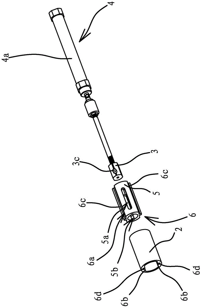
[0037] The structure and principle of this embodiment are basically the same as that of Embodiment 1, the difference is that: Figure 4 As shown, the inner end surface of the pusher rod 3 has a columnar pusher portion 3a protruding from the end face, the number of pusher portions 3a is two, and there is a gap 3b between the two pusher portions 3a.

[0038] When feeding a special-shaped workpiece, one end of the workpiece is columnar or cylindrical, and the other end has a convex body protruding from the end surface. When the ordinary feeding mechanism is pushing, the workpiece is easy to swing, and accurate and stable feeding cannot be realized. When using this pushing assembly for pushing, the two pushing parts 3a are all against the end face of the workpiece, the convex body of the workpiece is located in the gap 3b, and the workpiece is pushed out along the axis of the feeding cylinder 2, so that the The pushing mechanism in the workpiece feeding device can feed the workpie...


PUM


Abstract

The invention provides a pushing component in a feeding device, belongs to the technical field of parts of machine tools, and solves the problem that workpieces easily fall to cause missed machining when the conventional pushing component pushes materials. The pushing component in the feeding device comprises a support and a feeding cylinder arranged on the support; a pushing rod is arranged in the feeding cylinder; the support is further provided with a driving mechanism which drives the pushing rod to shift in a reciprocating manner; a feeding inner sleeve is arranged in the feeding cylinder in a penetrating manner; the pushing rod is arranged in the feeding inner sleeve in a penetrating manner; the side wall of the feeding inner sleeve is provided with strip-shaped through holes which are arranged along the axial direction of the feeding inner sleeve; the side wall of the pushing rod is provided with protruding convex bodies which are embedded in the strip-shaped through holes. The pushing component in the feeding device has the advantage that workpieces which are not machined are prevented from falling to avoid missing.

Description

technical field [0001] The invention belongs to the technical field of machine tool components, and relates to a feeding device, in particular to a pushing assembly in the feeding device. Background technique [0002] Machine tools are commonly used equipment for metal processing. At present, most of the machine tools are manually operated, and the processing procedures such as loading, clamping, cutting, loosening, and blanking of the workpiece are performed manually. The efficiency is low and the technical requirements for workers are high. Non-technical personnel cannot operate. Since a machine tool needs to be controlled by one person, a large number of technical personnel are required, resulting in high labor costs for business operations. Long-term work is labor-intensive, and workers are prone to fatigue, resulting in unstable product accuracy. [0003] For this situation, people have been aware of this deficiency and have made improvements, such as a workpiece feedin...

Claims


Application Information

Patent Timeline
Patent Type & Authority Patents(China)
IPC IPC(8): B23Q7/06
CPCB23Q7/06
Inventor 杨建龙
Owner JINING XINRUIDA INFORMATION TECH CO LTD
Why Eureka
Try Eureka