On-vehicle radar device

a technology for vehicle radar and vehicle, which is applied in the direction of measurement devices, using reradiation, instruments, etc., can solve the problems of difficult follow-up of the vehicle in front, detection errors may occur, and the vehicle in front existing at the center area of the detection range is difficult to detect, so as to achieve easy detection and easy detection

Active Publication Date: 2008-07-17
DENSO TEN LTD
View PDF12 Cites 44 Cited by
  • Summary
  • Abstract
  • Description
  • Claims
  • Application Information

AI Technical Summary

Benefits of technology

[0041]By decreasing the threshold for an object that is rapidly approaching based on a detected relative velocity, an obstacle can be easily detected and a pre-crash system can be supported. Also by decreasing the threshold of an object of which relative velocity is low, a vehicle traveling in front at about the same velocity can be easily detected, and cruise control can be supported.

Problems solved by technology

With such detection methods, however, the vehicle in front existing at the center area of the detection range is hard to be detected.
Since this means to increase the threshold in the center area, where the probability of detecting a vehicle in front is high, it causes a detection omission of a vehicle in front, and makes follow up of the vehicle in front difficult in an active cruise control system where detection of a vehicle in front to be followed up is critical.
Also in such a traveling situation as a curve, a vehicle traveling in front on the same lane may be miss-detected as a vehicle traveling in front on a different lane, and a detection error may occur.
However a method of setting thresholds for supplying information according to the change of the situation of the vehicle has not been proposed.

Method used


Image

  • On-vehicle radar device
  • On-vehicle radar device
  • On-vehicle radar device

Examples


first embodiment

of On-Vehicle Radar Device

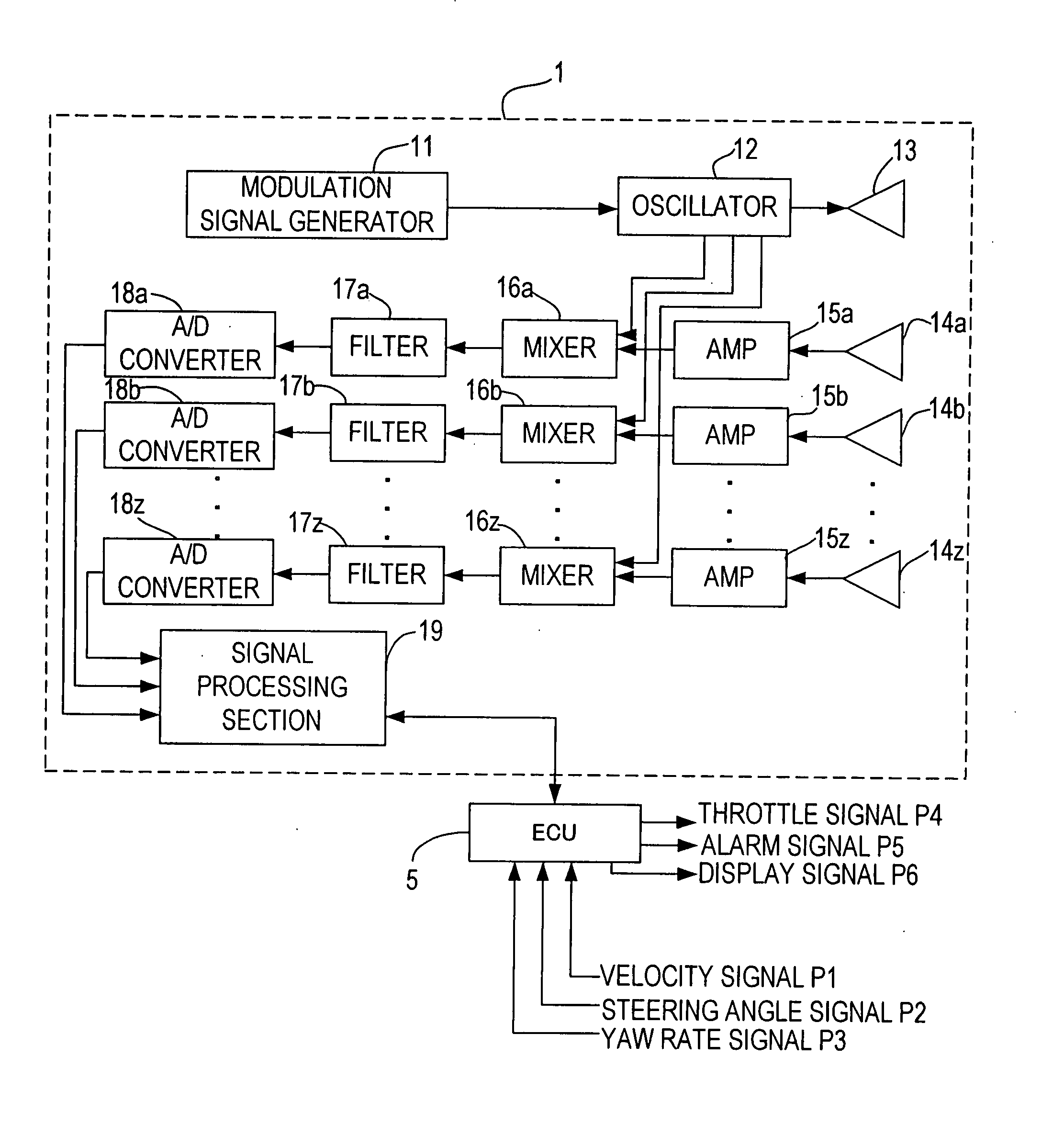
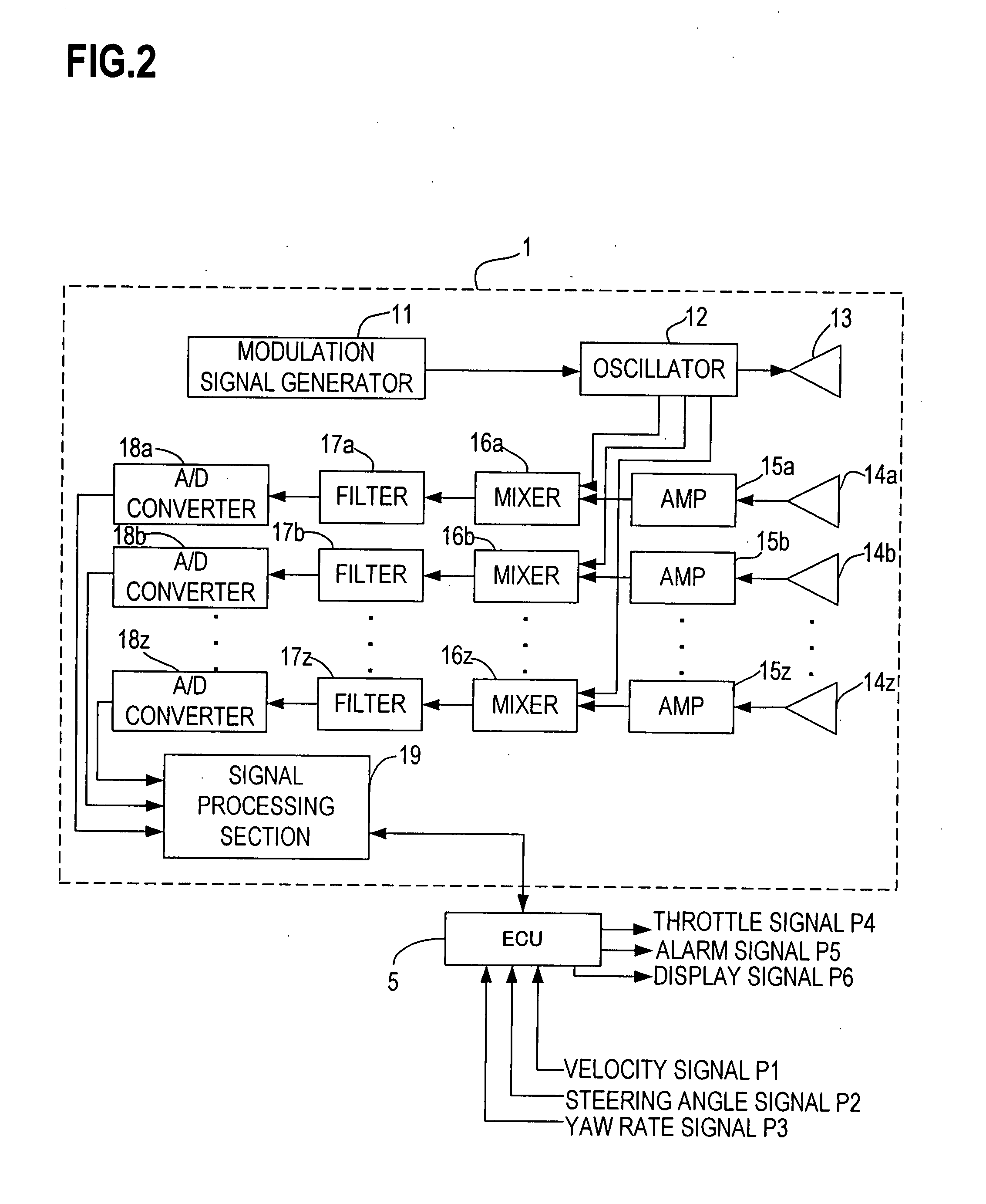
[0064]FIG. 2 is a block diagram depicting an on-vehicle radar device according to the first embodiment of the present invention, FIG. 3 is a diagram depicting the observation of a vehicle in front of an on-vehicle radar device, and FIG. 4 is a diagram depicting the relationship of the transmission wave and the receive wave to be applied FMCW as signal system of the on-vehicle radar device.

[0065]As FIG. 3 shows, an on-vehicle radar device 1 is installed on the front part of a vehicle 2, and detects a vehicle 4 in front by transmitting a radio wave in a millimeter wave area throughout a detection range 3 and receiving a reflected wave form the vehicle in front. The on-vehicle radar device 1 also detects obstacles when the obstacle exists in this peripheral area.

[0066]As FIG. 2 shows, a transmission system of the on-vehicle radar deice 1 installed on the vehicle 2 is comprised of a modulation signal generation 11, an RF oscillator (VCO) 12, and a transmission ...

second embodiment

of On-Vehicle Radar Device

[0088]An example of setting a threshold according to the velocity of the vehicle mounting the radar device of the present invention will now be described as the second embodiment. In this case, there are three types of threshold setting modes. An on-vehicle radar device 1 according to this embodiment has a configuration the same as the on-vehicle radar device 1 according to the first embodiment. In the following description, FIG. 8 to FIG. 10 are used.

[0089]FIG. 8, FIG. 9 and FIG. 10 are examples for setting thresholds based on the traveling velocity. FIG. 8 was used for describing the first embodiment, but will also be used for describing the second embodiment since the way of setting thresholds is virtually the same.

[0090]In this example, a velocity signal P1 is input to the on-vehicle radar device 1 of the present invention via the ECU 5. A signal processing section 19 sets a threshold based on the velocity signal P1.

[0091]FIG. 8 is an example of thresho...

third embodiment

of On-Vehicle Radar Device

[0105]FIG. 12 is a block diagram depicting an example of the connections of the on-vehicle radar device with another device according to the third embodiment of the present invention. The on-vehicle radar device 1 in FIG. 12 has a configuration the same as the on-vehicle radar device 1 according to the first embodiment. So a detailed description of the on-vehicle radar device 1 is omitted. To the on-vehicle radar device 1 of the present embodiment, a road shape recognition device 6 is connected.

[0106]The road shape recognition device 6 is comprised of a camera device 61 and an image processing device 62. In this case, the camera device 61 captures the image in front of the vehicle 2, and supplies it to the image processing device 62. This image is used for recognizing the white line on the road.

[0107]In other words, the image processing device 62 receives an image signal from the camera device 61, recognizes the white line on the road, and supplies the posi...


PUM


Abstract

An on-vehicle radar device has a transmission section for transmitting a radio wave to an object, a receive section for receiving the radio wave reflected by the object, and a processing section for dividing an object detection range into three or more of a plurality of areas, setting a threshold of an intensity of the radio wave received for each of the plurality of areas, and judging the existence of an object by comparing the intensity of the radio wave and the threshold. This processing section sets, based on an auto-cruise control mode or pre-crash mode of the vehicle, a threshold of a part of an area in the object detection range to be lower than the threshold of the other areas, or changes the threshold of the detection area according to the object detection status.

Description

CROSS-REFERENCE TO RELATED APPLICATIONS[0001]This application is based upon and claims the benefit of priority from the prior Japanese Patent Application No. 2006-216327, filed on Aug. 9, 2006, the entire contents of which are incorporated herein by reference.BACKGROUND OF THE INVENTION[0002]1. Field of the Invention[0003]The present invention relates to an on-vehicle radar device for detecting an object in front by radio waves, and more particularly to an on-vehicle radar device which sets a threshold of reflection wave intensity from an object for each area, and detects an object based on the threshold being set.[0004]2. Description of the Related Art[0005]On-vehicle radar devices installed on the front of a vehicle to measure a distance to an object from the front of the vehicle and a relative velocity of the vehicle and the object have been proposed. By measuring the distance up to the object and the relative velocity, an alarm device for warning of an impending collision with a...

Claims


Application Information

Patent Timeline
Patent Type & Authority Applications(United States)
IPC IPC(8): G01S13/00G01S13/931
CPCG01S7/2922G01S13/931G01S2013/9353G01S2013/9375G01S2013/935G01S2013/9357G01S2013/9321G01S2013/9319G01S2013/9322G01S2013/93271G01S2013/932
Inventor TSUCHIHASHI, MASATAKASHIMA, NOBUKAZUSHIRAKAWA, KAZUO
Owner DENSO TEN LTD
Why Eureka
Try Eureka