Blow-by Gas Passage Structure

一种窜气、通路的技术,应用在曲轴箱通风、发动机元件、机器/发动机等方向,能够解决油成分分离效率下降、阻挡效果下降等问题,达到防止窜气通过间隙、提高阻挡效果的效果

Active Publication Date: 2016-11-23
TOYOTA BOSHOKU KK
View PDF9 Cites 4 Cited by
  • Summary
  • Abstract
  • Description
  • Claims
  • Application Information

AI Technical Summary

Problems solved by technology

As a result, the blocking effect of the blow-by gas decreases, resulting in a decrease in the separation efficiency of the oil component in the blow-by gas

Method used


Image

  • Blow-by Gas Passage Structure
  • Blow-by Gas Passage Structure
  • Blow-by Gas Passage Structure

Examples


Embodiment 1

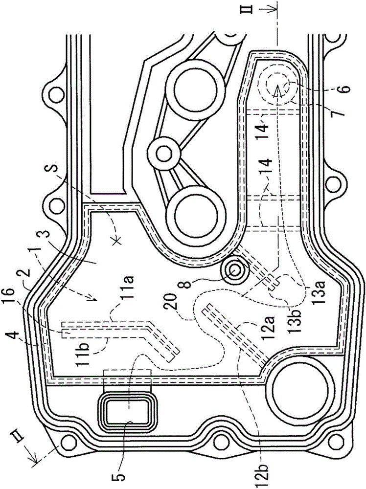
[0042] (1) The structure of the channel structure of the blow-by gas

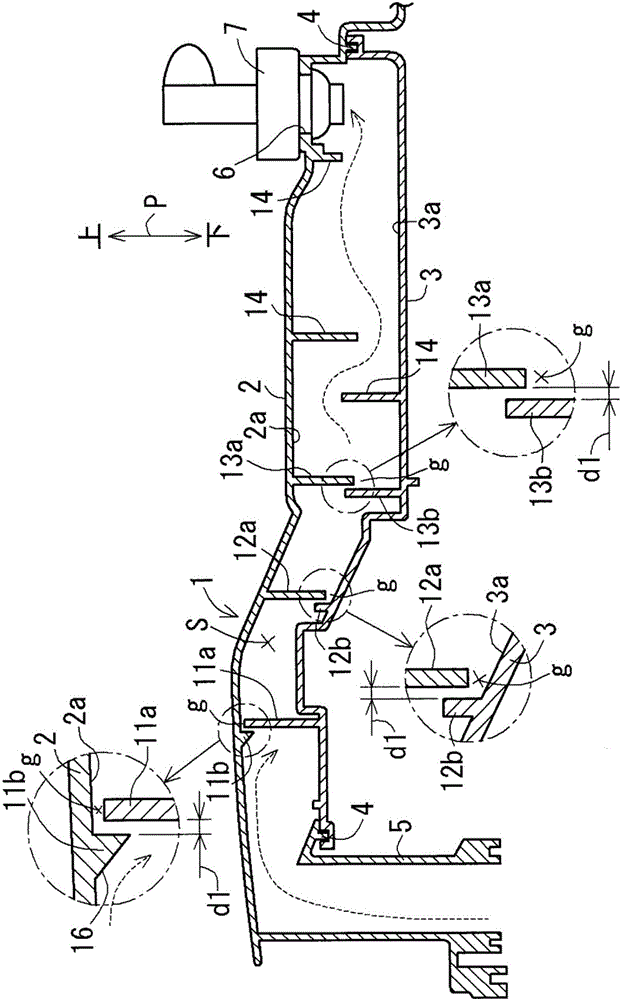
[0043] Such as figure 1 and figure 2 As shown, the blow-by gas passage structure 1 of this embodiment is provided in the separation chamber S formed between the cylinder head cover 2 and the baffle plate 3 . The passage structure 1 for blow-by gas constitutes a passage for the blow-by gas introduced into the separation chamber S. As shown in FIG.

[0044] The cylinder head cover 2 is formed of a resin material, and is formed in a box shape with an open bottom. In addition, the baffle plate 3 is formed of a resin material, and is joined to the head cover 2 at a welded portion 4 so as to close the bottom side of the head cover 2 by vibration welding. In addition, the head cover 2 and the baffle plate 3 respectively include facing surfaces 2 a , 3 a that face each other in the vertical direction P of the head cover 2 . In addition, a planar direction substantially perpendicular to the vertical direction ...

Embodiment 2

[0062] Next, the channel structure of the blow-by gas in the second embodiment will be described. In addition, in the blow-by gas passage structure of the present embodiment 2, structural parts substantially the same as those of the blow-by gas passage structure 1 of the above-mentioned embodiment 1 are denoted by the same reference numerals, and detailed description thereof will be omitted.

[0063] (1) The structure of the channel structure of the blow-by gas

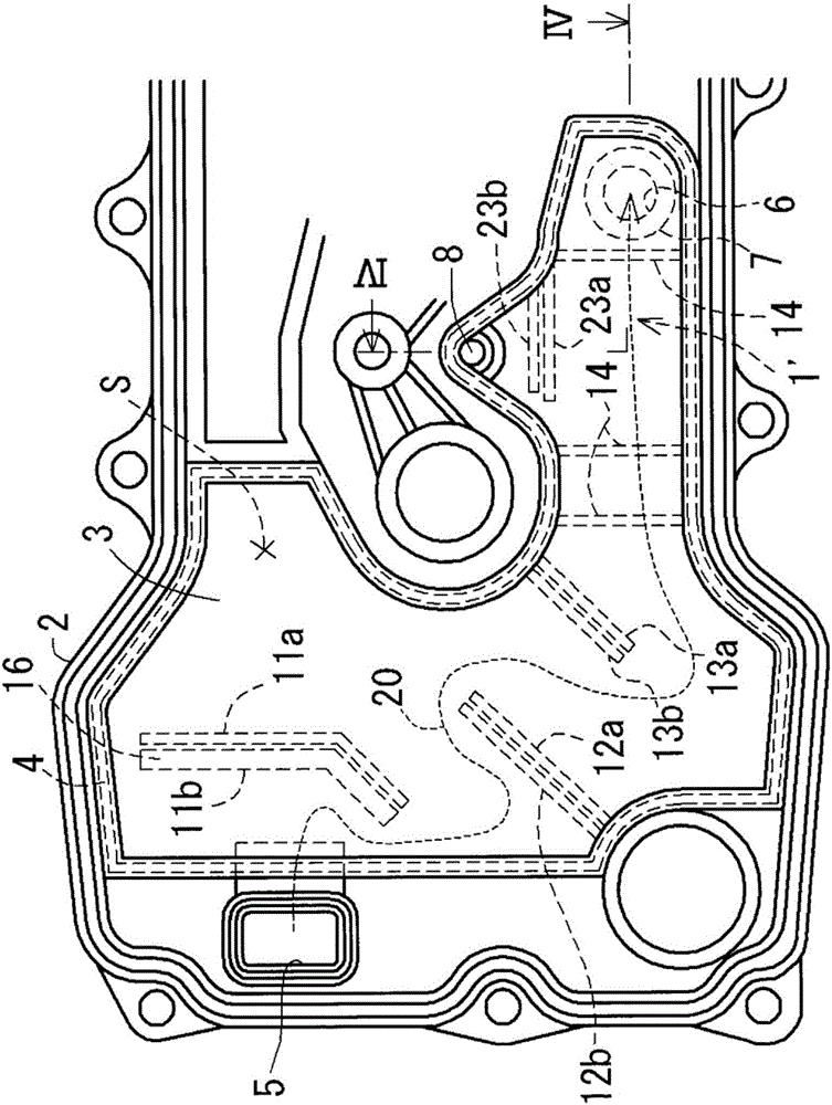
[0064] Such as image 3 and Figure 4 As shown, the blow-by gas passage structure 1' of this embodiment is provided in the separation chamber S formed between the cylinder head cover 2 and the baffle plate 3. An oil leak hole 8 is formed in the baffle plate 3 in the vicinity of the discharge port 6 (that is, the PCV valve 7 ) of the head cover 2 .

[0065] The blow-by gas passage structure 1' includes first ribs 11a, 12a, 13a and second ribs 11b, 12b, 13b for detour, rib 14 for detour, and first rib 23a and second ri...


PUM


Abstract

The present invention provides a blow-by gas passage structure which can improve the separation efficiency of the oil component contained in a blow-by gas. The blow-by gas passage structure is provided inside a separator chamber that is formed between a cylinder head cover and a baffle plate joined to the cylinder head cover by vibration welding. A first rib is provided on the opposite surface of one member of the cylinder head cover and the baffle plate, while a second rib is provided on the opposite surface of the other member, at positions upstream of the first rib in the flow of the blow-by gas and adjacent a gap formed between the distal end of the first rib and the opposite surface of the other member. The second rib has a height that is equal to or larger than the height of the gap so as to prevent passing of the blow-by gas through the gap.

Description

technical field [0001] The present invention relates to a passage structure of blow-by gas, and more specifically, relates to a passage of blow-by gas provided in a separation chamber formed between a cylinder head cover and a baffle plate joined to the cylinder head cover by vibration welding structure. Background technique [0002] As a conventional oil mist separator, an oil mist separator provided in a separation chamber formed between a cylinder head cover and a baffle plate joined to the cylinder head cover by vibration welding is generally known (for example, refer to Japanese Patent Laid-Open No. 2011- Bulletin No. 58433). In this conventional oil mist separator, for example, as Figure 5 and Figure 6 As shown, on the surface of the cylinder head cover 102 and / or the baffle plate 103, detour ribs 111 for detouring (snaking) the blow-by gas in the separation chamber S along the planar direction are erected. Then, the blow-by gas introduced into the separation cham...

Claims


Application Information

Patent Timeline
Patent Type & Authority Applications(China)
IPC IPC(8): F01M13/04
CPCF01M13/0405F01M13/0416F01M2013/0461F02F7/006
Inventor 名和辉好
Owner TOYOTA BOSHOKU KK
Why Eureka
Try Eureka