A structure for selecting the rotation angle of a shift fork for a worm gear reducer

A worm gear and reducer technology, which is applied to belts/chains/gears, components with teeth, mechanical equipment, etc., can solve the problems of large cost investment, complex limit design, poor versatility, etc., and achieve a simple limit structure. , low cost input, good versatility

Active Publication Date: 2018-07-31
DIBAISHI MOTOR TECH SUZHOU CO LTD
View PDF9 Cites 0 Cited by
  • Summary
  • Abstract
  • Description
  • Claims
  • Application Information

AI Technical Summary

Problems solved by technology

[0004] The purpose of the present invention is to provide a structure for selecting the rotation angle of a shift fork for a worm gear reducer, which can solve the problems of limited use occasions, poor versatility, complicated limit design, and large cost investment of the worm gear reducer in the prior art.

Method used


Image

  • A structure for selecting the rotation angle of a shift fork for a worm gear reducer
  • A structure for selecting the rotation angle of a shift fork for a worm gear reducer

Examples


Embodiment Construction

[0017] In order to deepen the understanding of the present invention, the present invention will be further described below in conjunction with the embodiments and accompanying drawings. The embodiments are only used to explain the present invention and do not constitute a limitation to the protection scope of the present invention.

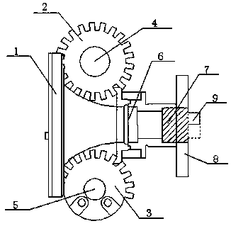
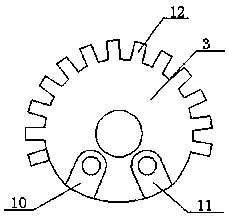
[0018] Such as figure 1 and figure 2 A worm gear reducer shown with a shift fork selects the rotation angle structure, including a base 1, a complete tooth worm gear 2, an incomplete tooth worm gear 3, a worm 6 and a shift fork 7, a complete tooth worm gear 2 and an incomplete tooth worm gear 3 respectively Connect shaft I4 and shaft II5, shaft I4 and shaft II5 are respectively installed on the base 1 through bearings, the end of the worm 6 is connected to the shift fork 7, the beginning of the worm 6 is set between the complete tooth worm gear 2 and the incomplete tooth worm gear 3, The complete-tooth worm gear 2 and the incomplete-tooth worm ...


PUM


Abstract

The invention discloses a structure for selecting a rotation angle by a shifting fork for a worm gear-worm reducer. The structure comprises a base, a complete-tooth worm gear, an incomplete-tooth worm gear, a worm and the shifting fork, wherein the complete-tooth worm gear and the incomplete-tooth worm gear are respectively connected to a shaft I and a shaft II; the shaft I and the shaft II are both mounted on the base via bearings; the tail end of the worm is connected to the shifting fork; the initial end of the worm is arranged between the complete-tooth worm gear and the incomplete-tooth worm gear; the complete-tooth worm gear and the incomplete-tooth worm gear are symmetrically distributed at two sides of the worm; and the shifting fork is arranged on a sliding groove and moves upwards and downwards under the action of a driving mechanism. According to the invention, the complete-tooth worm gear and the incomplete-tooth worm gear are both arranged on the worm gear-worm reducer, and the adopted shifting fork moves upwards and downwards to enable the worm to choose to be meshed with any one of the complete-tooth worm gear and the incomplete-tooth worm gear, so that the change of the rotation angle of the worm gear-worm reducer is realized, and the universality is good; and a difference between the complete-tooth worm gear and the incomplete-tooth worm gear is that whether a stopping sheet exists, so that the cost input is low.

Description

technical field [0001] The invention relates to the technical field of worm gear reducers, in particular to a structure for selecting a rotation angle of a shift fork for a worm gear reducer. Background technique [0002] At present, worm gear transmission is widely used in various reduction transmission devices due to its characteristics of large transmission ratio, stable transmission, and self-locking. In the prior art, the general worm gear reducer mostly rotates 360°, but for some application occasions, the rotation angle of the worm gear does not need to be as large as 360°, thus causing the existing worm gear The defect of poor versatility, such as a single-axis tracking solar power station only needs a rotation angle range of ±60°, if you want to use a worm gear reducer with a rotation angle of 360°, you need to add a limit design on the worm gear, which makes the cost large The amplitude increases, and the worm wheel has teeth at 360°, some teeth are not used in us...

Claims


Application Information

Patent Timeline
Patent Type & Authority Patents(China)
IPC IPC(8): F16H63/28F16H63/30
CPCF16H63/28F16H63/30
Inventor 王凯
Owner DIBAISHI MOTOR TECH SUZHOU CO LTD
Why Eureka
Try Eureka