
Control valve used for water heater

A technology for controlling valves and water heaters, applied to valve devices, cocks including cut-off devices, engine components, etc., can solve the problems of unsmooth sewage discharge from the mounting seat, reduction of the cross-sectional area of ​​the sewage flow, affecting the life of the heating pipe, etc. Simple and reasonable, the effect of improving sealing performance and reducing procurement costs

Inactive Publication Date: 2015-12-16
GUANGDONG WEBER ELECTRIC APPLIANCES
View PDF8 Cites 0 Cited by
  • Summary
  • Abstract
  • Description
  • Claims
  • Application Information

AI Technical Summary

Problems solved by technology

When installed on the heating tube flange, it is difficult to replace the magnesium rod, and it is close to the heating tube, which is easy to form scale accumulation and affect the life of the heating tube
When installed at the sewage outlet, the installation seat is likely to cause the phenomenon of unsmooth sewage discharge and water discharge, and the reduction of the cross-sectional area of ​​the sewage flow, which needs further improvement

Method used


Image

  • Control valve used for water heater
  • Control valve used for water heater
  • Control valve used for water heater

Examples


Embodiment Construction

[0023] Embodiments of the present invention are described in detail below, examples of which are shown in the drawings, wherein the same or similar reference numerals designate the same or similar elements or elements having the same or similar functions throughout. The embodiments described below by referring to the figures are exemplary only for explaining the present invention and should not be construed as limiting the present invention.

[0024] In describing the present invention, it is to be understood that the terms "front and rear", "upper", "lower", "left", "right", "vertical", "horizontal", "inner", "outer" etc. indicate The orientation or positional relationship is based on the orientation or positional relationship shown in the drawings, and is only for the convenience of describing the present invention and simplifying the description, rather than indicating or implying that the referred device or element must have a specific orientation or be configured in a spec...


PUM


Abstract

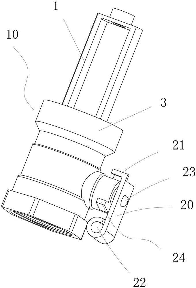
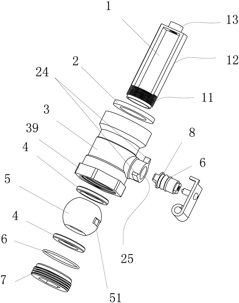
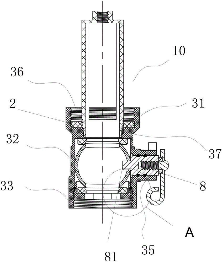
The invention discloses a control valve used for a water heater. The control valve is installed on a water valve, the water valve comprises a valve body, a valve cavity and a valve element, and the valve element is arranged inside the valve cavity. A tubular flange extends outwards on the side wall of the valve body to form an adjusting cavity, a rotating shaft is arranged inside the adjusting cavity, one end of the rotating shaft is connected with the valve element, and the other end of the rotating shaft is connected with a handle. A limiting poking rod is arranged on the handle, limiting blocks are arranged on the outer side wall of the tubular flange, and the limiting poking rod extends into the travel region between the two limiting blocks. The control valve used for the water heater is simple and reasonable, and the opening and closing limiting structure of the valve is scientific in design and high in practicability. The end of the poking rod on the handle of the water valve is curled inwards to form a sleeve into which an assistance tool can be inserted, and using is quite convenient.

Description

technical field [0001] The invention relates to the technical field of electric water heaters, in particular to a control valve applied to water heaters. Background technique [0002] The storage type electric water heater will inevitably form scale during use, and the dirt will be deposited on the bottom of the inner tank after long-term use. Therefore, in addition to the water inlet and outlet, the inner tank of the existing water storage type electric water heater is generally also provided with a sewage outlet, and a sewage valve is installed on the sewage outlet for the user to carry out sewage treatment to the water heater inner tank on a regular basis. However, the structure of the existing blowdown valve for water heaters is quite complicated, and there are many corresponding parts and components. The installation and disassembly require professional tools, and usually need to rely on professionals to come to handle it, thereby bringing inconvenience to users. [00...

Claims


Application Information

Patent Timeline
Patent Type & Authority Applications(China)
IPC IPC(8): F16K5/06F16K5/08
CPCF16K5/06F16K5/08
Inventor 欧永源劳子峰吴宇翔董越刘庆
Owner GUANGDONG WEBER ELECTRIC APPLIANCES
Learn More