Spiral squeezing type sludge dewatering equipment

A technology of sludge dewatering machine and screw extrusion, which is applied in the direction of dehydration/drying/concentrated sludge treatment, etc. It can solve the problems of easily clogging the gap between the static filter and the dynamic filter, reducing the service life of the device, and reducing the overall dehydration effect. , to achieve the effect of scientific water inlet and outlet channels, precise adjustment and simple structure

Inactive Publication Date: 2008-12-31
浙江德安新技术发展有限公司
View PDF2 Cites 18 Cited by
  • Summary
  • Abstract
  • Description
  • Claims
  • Application Information

AI Technical Summary

Problems solved by technology

[0003] This technical solution has the following defects: First, in the technical solution disclosed by this patent, the sludge passes through the gap between the static filter and the dynamic filter in the sliding filter group, which will easily block the static filter and the dynamic filter. The gap between the sheets, and the sludge itself is some particles and impurities, which will constantly rub against the surfaces of the static filter and the moving filter in reverse, causing serious wear and directly reducing the service life of the device. Therefore, this This dehydration method, in which the sludge is discharged from the periphery and the water is discharged from the center, is not scientific and reasonable enough and needs to be improved; secondly, the blades in the spiral discharge mechanism are driven to rotate by the screw frame fixed together with it, and the static in the sliding filter group The filter is fixed on the spiral frame and rotates with it, while the moving filter in the sliding filter group is moved relatively by the driving arm welded with the central shaft, at the same time, the rotation of the static filter and the moving filter The direction is opposite, that is, the screw rack and the central axis in the screw discharge mechanism must rotate in the opposite direction, which means that the device needs two power sources with opposite rotation directions, and the sludge between the static filter and the dynamic filter gap It will increase the friction between the two. To make the rotation direction of the static filter and the moving filter opposite, the energy consumption required is v

Method used


Image

  • Spiral squeezing type sludge dewatering equipment
  • Spiral squeezing type sludge dewatering equipment
  • Spiral squeezing type sludge dewatering equipment

Examples


Example Embodiment

[0027] The present invention will be further described in detail below with reference to the embodiments of the drawings.

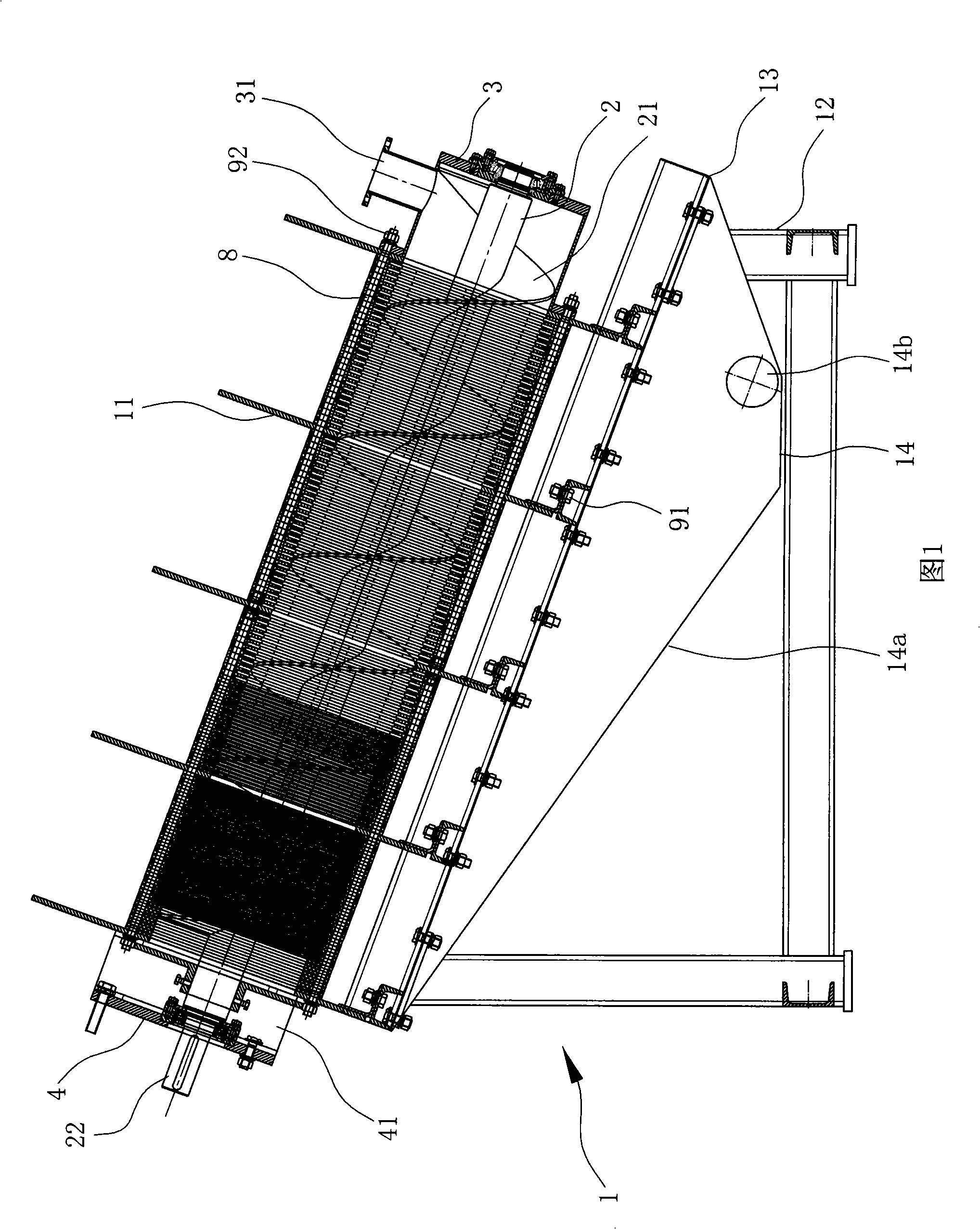
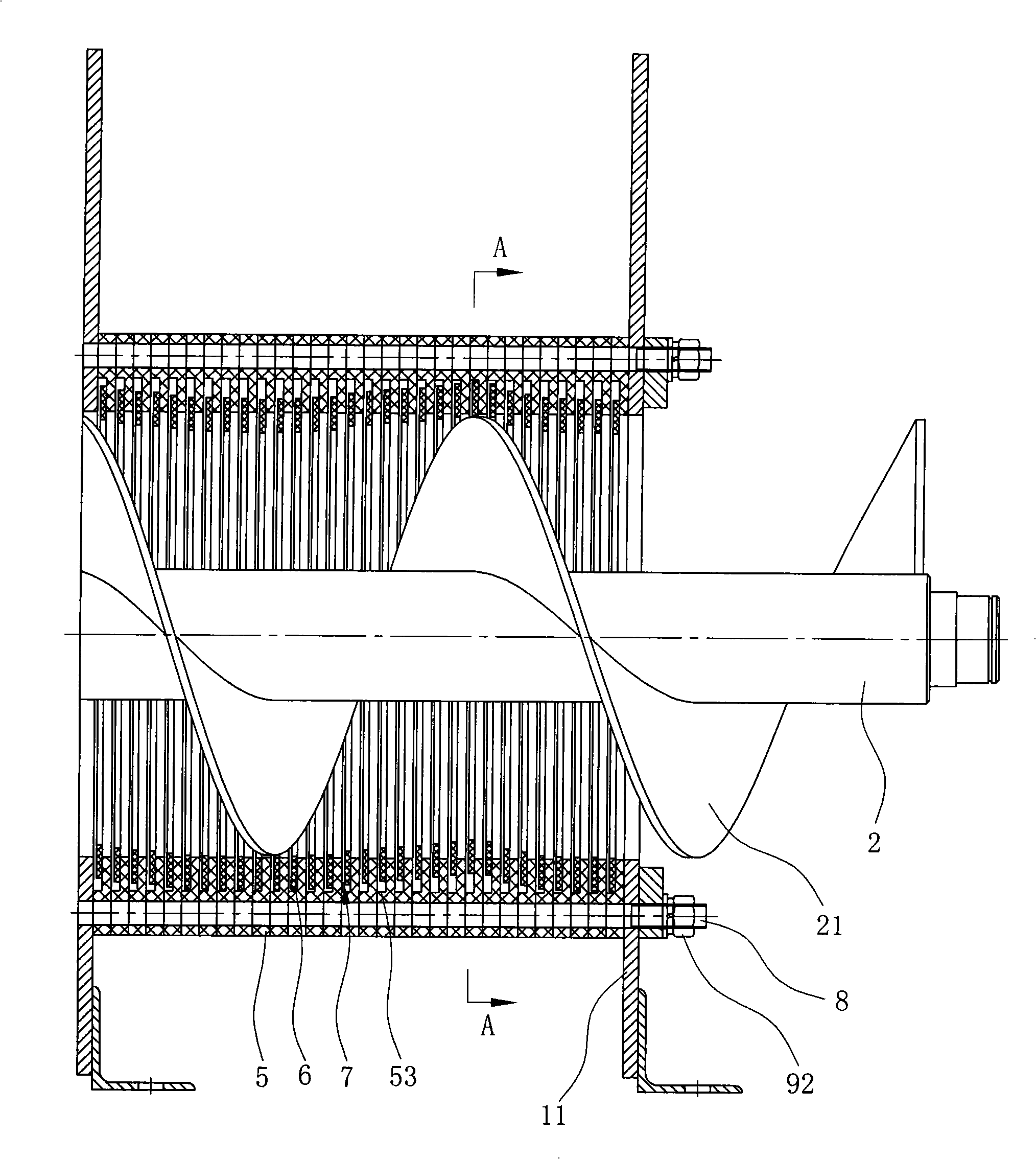
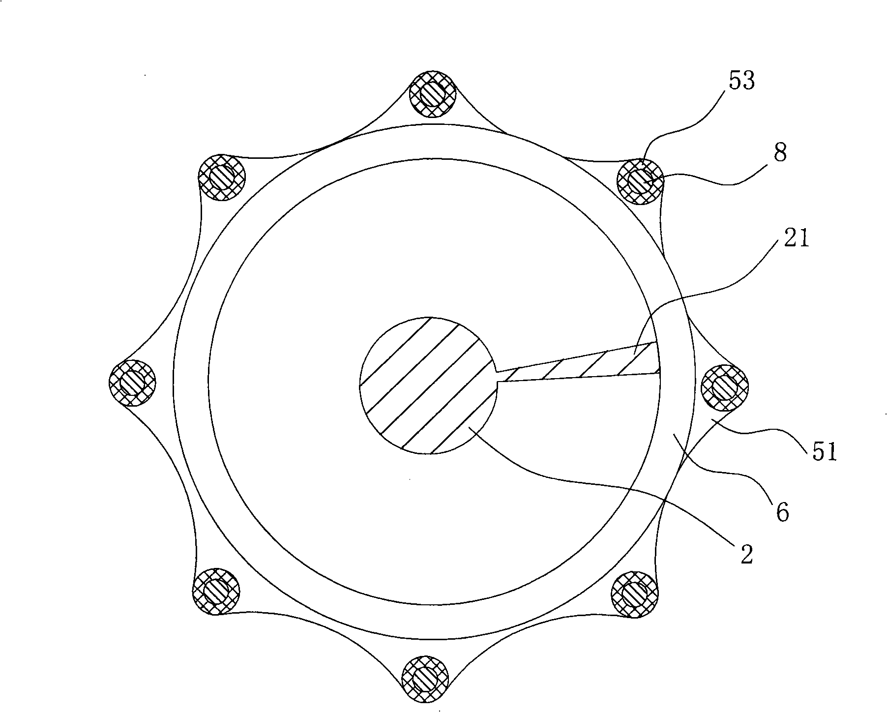
[0028] As shown in Figures 1 to 5, the screw extrusion sludge dewatering machine includes an organic seat 1, a water inlet, a sludge outlet 41, a water outlet, and a spiral blade 21 that penetrates the frame 1 and has spiral blades 21 on the periphery. The screw shaft 2, a motor that drives the screw shaft 2 to rotate, and a filter pack set on the periphery of the screw shaft 2 by a plurality of ring-shaped static filters 5 and ring-shaped moving filters 6 arranged at intervals;

[0029] Wherein, the base 1 includes a bracket and a plurality of supporting plates 11 arranged in parallel fixed on the bracket. In this embodiment, the supporting plate 11 is provided with four pieces, and the bracket includes legs 12 and a plurality of supporting plates 11 arranged in parallel. The fixed frame 13 with the top and the rear end of the leg 12 inclined downward, and e...


PUM


Abstract

The invention discloses a screw extrusion type sludge dewatering machine, comprising a machine base (1), a water inlet part, a sludge exit part (41), a water outlet part, a screw shaft (2) with a spiral blade (21), as well as a filter disc assembly composed of a plurality of annular static filter discs (5) and annular dynamic filter discs (6) in a cross-interval arrangement; wherein, each static filter disc (5) is fixed relatively to the machine base (1); the internal diameter of each dynamic filter disc (6) coincides with the external diameter of the blade (21) and has line contact with the blade (21); moreover, the space between two adjacent static filter discs (5) is slightly greater than the thickness of the dynamic filter disc (6) between the two adjacent static filter discs (5) so as to form a gap (7) between the static filter discs (5) and the dynamic filter disc (5); water can flow through the gap (7). Compared with the prior art, the invention enables water to directly flow out through the gaps of the filter disc assembly so as to avoid the abrasion to the static filter discs and the dynamic filter discs caused by sludge; the device has a longer service lifer and adopts only one power source to realize solid-liquid separation, so that the energy consumption is lower; besides, the components of the device are easy to install and simple in structure to facilitate actual implementation.

Description

technical field [0001] The invention relates to a device for solid-liquid separation of sewage and sludge, in particular to a screw extrusion sludge dehydrator. Background technique [0002] Existing devices for solid-liquid separation include vacuum filters, pressurized filters, centrifugal dehydrators, belt filter presses, plate-and-frame filter presses, etc. Due to the use of filter screens, sludge It is easy to stay in the mesh of the filter screen to block the filter screen, reduce the efficiency of solid-liquid separation, and the service life is short, which also brings a lot of trouble to the maintenance work of the device. Therefore, a new screw extrusion sludge dewatering machine is invented, such as the Chinese invention patent "Laminated Screw Dewatering Machine" whose patent number is ZL98124476. . The laminated screw dehydrator includes a shell, a screw shaft inside the shell, blades driven by the screw shaft and a sliding filter group arranged in the center ...

Claims


Application Information

Patent Timeline
IPC IPC(8): C02F11/12
Inventor 俞建德
Owner 浙江德安新技术发展有限公司
Why Eureka
Try Eureka