Large temperature difference heat exchange method and large temperature difference heat exchange device capable of reducing return water temperature of heat supply network

A technology of return water temperature and heat exchange device, which can be used in heating methods, hot water central heating systems, and household heating, etc., and can solve problems such as insufficient heat supply in the heating pipe network.

Inactive Publication Date: 2016-11-23
HIT HARBIN INST OF TECH KINT TECH
View PDF5 Cites 0 Cited by
  • Summary
  • Abstract
  • Description
  • Claims
  • Application Information

AI Technical Summary

Problems solved by technology

[0013] Aiming at newly building or renovating the old heating pipe network and solving the problem of insufficient heat supply generally existing in the heating pipe network, the present invention provides a method that can...

Method used


Image

  • Large temperature difference heat exchange method and large temperature difference heat exchange device capable of reducing return water temperature of heat supply network
  • Large temperature difference heat exchange method and large temperature difference heat exchange device capable of reducing return water temperature of heat supply network
  • Large temperature difference heat exchange method and large temperature difference heat exchange device capable of reducing return water temperature of heat supply network

Examples


Embodiment Construction

[0032] The present invention will be described in further detail below in conjunction with the accompanying drawings and embodiments.

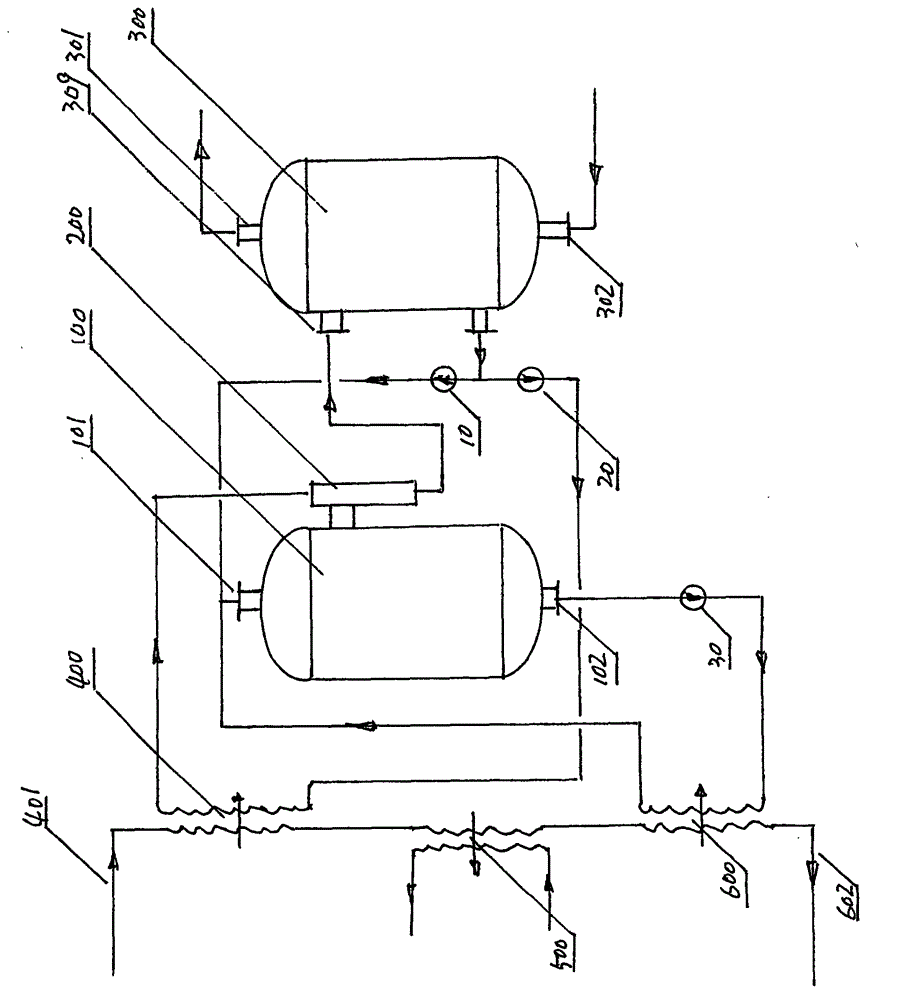
[0033] figure 1 A schematic diagram of the large temperature difference heat exchange method for reducing the return water temperature of the heating network is given.

[0034] Compared with the schematic diagram of large temperature difference heat transfer in the figure, the specific steps of the large temperature difference heat transfer method are as follows:

[0035] 1. The high-temperature incoming water of about 90°C from the heating pipe network enters the high-temperature heat exchanger 400 through the hot water inlet 401;

[0036] 2. The high-temperature heat exchanger 400 is a partition-type heat exchanger. The high-temperature incoming water passes through the partition wall of the heat exchanger to heat the high-pressure Freon on the other side, and the Freon evaporates and overheats when heated, and then flows out;

[0037] 3. ...


PUM


Abstract

The invention provides a large temperature difference heat exchange method and a large temperature difference heat exchange device capable of reducing the return water temperature of a heat supply network to increase a heating load of the heat supply network. The large temperature difference heat exchange method and the large temperature difference heat exchange device are specially provided for a newly-built or rebuilt old heat supply network to solve the problem that the heating load of the old heat supply network is generally not sufficient. The large temperature difference heat exchange method comprises the following steps: incoming water of the heat supply network enters a high temperature heat exchanger and heats high pressure freon, produced high pressure freon vapor injects low pressure freon vapor in an evaporator through an ejector, freon vapor ejected by the ejector heats heating circulating water, the incoming water of the heat supply network flows out of the high temperature heat exchanger, then enters a middle temperature heat exchanger, heats the heating circulating water and then flows into a low temperature heat exchanger, the incoming water of the heat supply network releases heat to low temperature liquid freon, left after evaporation, from the evaporator, and the incoming water of the heat supply network releases heat for cooling for three times and then returns to a return water pipeline of the heat supply network. The large temperature difference heat exchange device comprises the high temperature heat exchanger, the middle temperature heat exchanger, the low temperature heat exchanger, the evaporator, a condenser, the ejector and three freon pumps.

Description

technical field [0001] The invention relates to thermal technology, in particular to a large temperature difference heat exchange method and device for reducing the return water temperature of a heating network. Background technique [0002] In recent years, with the continuous development of my country's urban construction, the contradiction between regional development and heating demand has become increasingly prominent. The urban area of ​​all cities is constantly expanding, the large-scale residential areas in the main urban area are constantly increasing, the area of ​​the old urban area is greatly increased every year, and the area of ​​the new urban area is also expanding. Judging from the current heat source and heating network heating capacity of the city, it is far from meeting the needs of the city's rapid development. If the heat supply cannot keep up, it will cause a bottleneck in urban development. [0003] In order to solve this contradiction concerning urb...

Claims


Application Information

Patent Timeline
IPC IPC(8): F24D3/16F24D19/10
Inventor 李伟李金峰尚德敏
Owner HIT HARBIN INST OF TECH KINT TECH
Why Eureka
Try Eureka