Mixed-flow air conditioner

A mixed-flow and air-conditioning technology, which is applied in air-conditioning systems, space heating and ventilation, space heating and ventilation details, etc., can solve the problems of increasing air-conditioning costs, large air-conditioning volume, etc., to improve comfort, ease air supply temperature, The effect of a simple structure

Inactive Publication Date: 2016-11-23
QINGDAO HAIER SMART TECH R & D CO LTD
View PDF4 Cites 3 Cited by
  • Summary
  • Abstract
  • Description
  • Claims
  • Application Information

AI Technical Summary

Problems solved by technology

However, this kind of drainage air conditioner requires a comprehensive transformation of the air duct structure and air outlet of the air conditioner, which increases the cost of the air conditioner, and the air conditioner is too large

Method used


Image

  • Mixed-flow air conditioner
  • Mixed-flow air conditioner
  • Mixed-flow air conditioner

Examples


Embodiment Construction

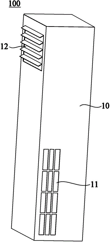
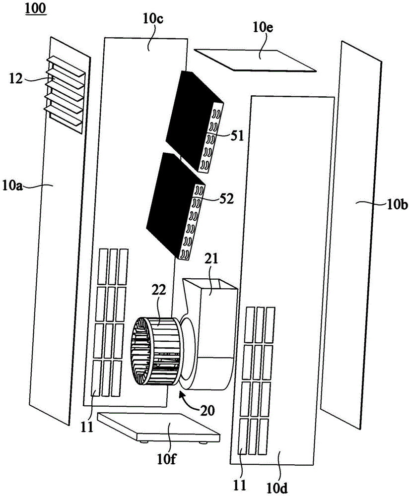
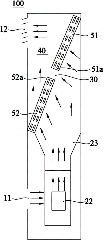
[0038] figure 1 is a schematic structural diagram of a mixed-flow air conditioner 100 according to an embodiment of the present invention, which includes a housing 10 . The housing 10 has an air inlet 11 for introducing air from the ambient space and an air outlet 12 for returning air to the ambient space. Specifically, the casing 10 may include a front side panel 10a, a rear side panel 10b, side panels 10c and 10d, an upper top panel 10e and a lower bottom panel 10f, the front side panel 10a, the rear side panel 10b, and the side panels 10c, which are independent from each other. and 10d, the upper top plate 10e and the lower bottom plate 10f are assembled and connected by fixing members such as screws to form a housing 10 with an internal space. Certainly, those skilled in the art can understand that, the rear side plate 10b, the side plates 10c and 10d, the upper top plate 10e and the lower bottom plate 10f of the housing 10 can also be integrally formed to form a semi-clo...


PUM


Abstract

The invention relates to a mixed-flow air conditioner which comprises a housing with an air inlet and an air outlet, a fan arranged in the housing and at least two evaporators. The fan is used for promoting air to flow towards the air outlet from the air inlet. At least two evaporators are arranged at the downstream of the fan; and a mixed-flow space for allowing air to mix is formed among the two evaporators and the air outlet. Each evaporator is provided with a heat exchange gap for allowing air to pass through and carrying out heat exchange; a direct-through gap for allowing air to directly pass through is formed between the two adjacent evaporators, so that air, which flows towards the air outlet under the action of the fan, flows into the mixed-flow space through the heat exchange gaps of the evaporators and the direct-through gap between two adjacent evaporators, and is fed into environmental space through the air outlet. The mixed-flow air conditioner can reduce the air outlet temperature of the air outlet, so that comfort level of the air conditioner is improved.

Description

technical field [0001] The invention relates to air conditioning technology, in particular to a mixed flow air conditioner. Background technique [0002] The air duct structure of a common air conditioner in the existing market is generally composed of an air inlet, a centrifugal fan, an evaporator and an air outlet. Indoor air enters the interior of the air conditioner from the air inlet, and after being centrifugally accelerated by the centrifugal fan, the air passes through the evaporator for heat exchange, and the air after heat exchange is blown into the room through the air outlet. However, the temperature of the cool air blown out from the air outlet is too low and not soft enough, and it will cause discomfort to the user when blown on the body. [0003] In order to solve the above technical problems, a drainage air conditioner has appeared in the prior art, which introduces a little indoor air at the air outlet of the air conditioner, and mixes it with the cool air ...

Claims


Application Information

Patent Timeline
IPC IPC(8): F24F1/00F24F13/30F24F13/06
Inventor 王晶刘德昌唐林强张立臣
Owner QINGDAO HAIER SMART TECH R & D CO LTD
Why Eureka
Try Eureka