Space positioning device, system and method

A technology of spatial positioning and spatial coordinates, which is applied in the field of computer vision, can solve the problems of demanding operating algorithm hardware environment, complex algorithms, and low recognition rate of the recognition system, and achieve the effects of improving image recognition rate, reducing complexity, and saving costs

Active Publication Date: 2016-11-23
SUPERD CO LTD
View PDF11 Cites 27 Cited by
  • Summary
  • Abstract
  • Description
  • Claims
  • Application Information

AI Technical Summary

Problems solved by technology

[0005] Due to the existence of the above problems, the recognition rate of the recognition system is low, the algorithm is complex, and the hardware environment for running the algorithm is demanding

Method used


Image

  • Space positioning device, system and method
  • Space positioning device, system and method
  • Space positioning device, system and method

Examples


Embodiment Construction

[0058] The present invention will be described in detail below in conjunction with the accompanying drawings and embodiments.

[0059] It should be noted that, if there is no conflict, the embodiments of the present invention and various features in the embodiments can be combined with each other, and all are within the protection scope of the present invention. In addition, although the functional modules are divided in the schematic diagram of the device, and the logical order is shown in the flowchart, in some cases, it may be different from the module division in the device, or the sequence shown or executed in the flowchart may be different. described steps.

[0060] The present invention will be described in detail below in conjunction with specific embodiments.

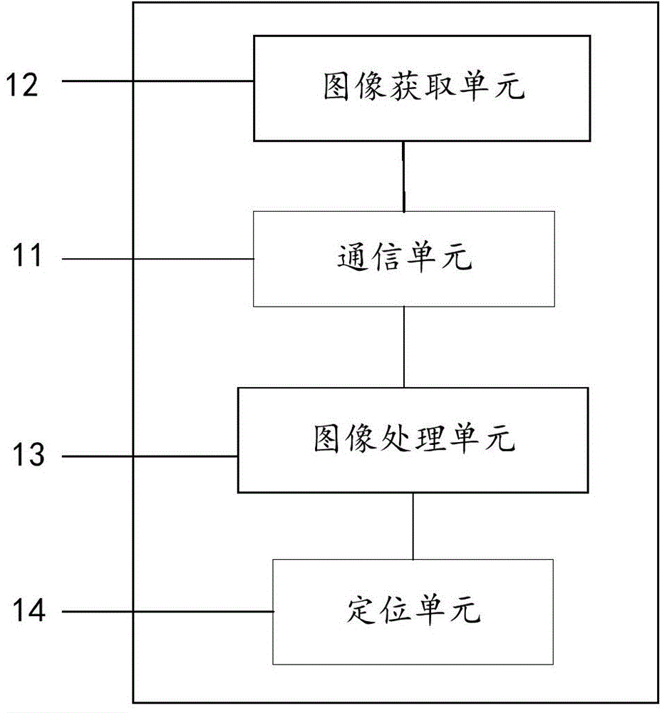
[0061] figure 1 It is a schematic diagram of the structure of the space positioning device according to the embodiment of the present invention, such as figure 1 As shown, the spatial positioning device incl...


PUM


Abstract

The invention discloses a space positioning device, system and method. The space positioning device comprises a communication unit for establishing communication with a positioning object; an image obtaining unit for obtaining a first stereo image of a background image under the condition that a mark point infrared light source of the positioning object is in an off state, and a second stereo image comprising a mark point under the condition that the mark point infrared light source is in an on state; an image processing unit for carrying out image processing on the first stereo image and the second stereo image to obtain a mark point light spot graph; and a positioning unit for obtaining a space coordinate of the mark point according to the mark point light spot graph. The space positioning device, system and method realize distinguishing between the object to be positioned and the background image, improve image recognition rate, reduce algorithm complexity, simplify algorithm operation environment and save cost.

Description

technical field [0001] The invention relates to the technical field of computer vision, in particular to a space positioning device, system and method thereof. Background technique [0002] Computer vision technology is a technical direction that has become increasingly mature with the development of image sensors and microprocessors recently. [0003] In computer vision technology, there is a method of reconstructing the three-dimensional information of the captured image by simulating the binocular disparity of the human eye with the left and right cameras installed at a certain distance. This method is called stereo matching in stereo vision. The disparity map is obtained mainly by finding the corresponding relationship between each image and according to the principle of triangulation; after obtaining the disparity information, the depth information and three-dimensional information of the original image can be easily obtained according to the projection model. [0004]...

Claims


Application Information

Patent Timeline
IPC IPC(8): G01B11/00
Inventor 蒋凌锋
Owner SUPERD CO LTD
Why Eureka
Try Eureka