Non-contact video displacement measuring method

A displacement measurement, non-contact technology, applied in photogrammetry/video metrology, measurement devices, radio wave measurement systems, etc., can solve the problems of complex instrument setup and high measurement costs

Inactive Publication Date: 2016-11-23
TONGJI UNIV
View PDF8 Cites 10 Cited by
  • Summary
  • Abstract
  • Description
  • Claims
  • Application Information

AI Technical Summary

Problems solved by technology

Existing non-contact measurement methods usually use high-frequency CCD shooting equipment to c

Method used


Image

  • Non-contact video displacement measuring method
  • Non-contact video displacement measuring method
  • Non-contact video displacement measuring method

Examples


Embodiment

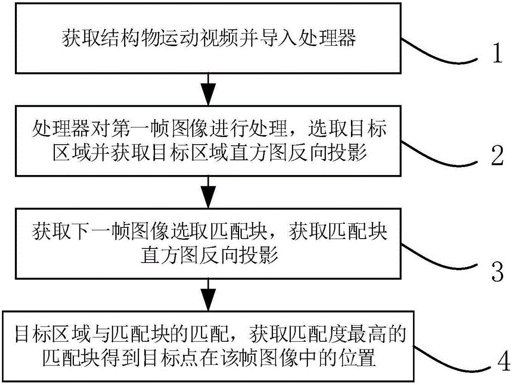
[0049] Such as figure 1 As shown, a non-contact video displacement measurement method includes the following steps:

[0050] Step 1: Use a digital device with video shooting function to shoot the motion video of the structure and import it into the processor, where the digital device includes a digital camera or a mobile phone;

[0051] Step 2: The processor obtains the first frame of image in the motion video and calibrates the target point, selects the target area with the target point as the center, and obtains the histogram back projection of the target area;

[0052] Step 3: The processor obtains the next frame of image in the motion video. The target point position in the previous frame of image is the center, and the image area larger than the target area is selected as the matching area. The matching area is selected to be 1.5 to 2 times the size of the target area. Each pixel in the matching area takes the pixel position as the center to obtain a matching block equal in siz...


PUM


Abstract

The invention relates to a non-contact video displacement measuring method. The method comprises the following steps that 1, motion videos of a digital equipment photographing structure are adopted and guided into a processor; 2, the processor obtains a first frame image in the motion videos, a target point is adopted as a center selection target area; 3, the next frame image is obtained, a target point in the previous image is adopted as a center selection matching area, pixel points in the matching area obtain matching blocks equal to the size of the target area by adopting the pixel point position as the center; 4, the target area and the matching blocks are matched to determine a matching block matched with the target area, the center point of the matching blocks is the position of the target point in the frame image, the position is adopted as a novel target point, and the matching blocks are adopted as the novel target area; 5, the steps 3 and 4 are repeatedly executed to obtain the position where the target point in each frame image is located, and a displacement curve of the target point is obtained. Compared with the prior art, measuring equipment is cheap, and the measuring result is reliable.

Description

Technical field [0001] The invention relates to a displacement measurement method, in particular to a non-contact video displacement measurement method. Background technique [0002] Engineering structure will produce deflection and displacement under load, and its size and direction reflect the rigidity, health and service status of the structure. The observation of deflection and displacement is to measure the deformation of the structure or component through displacement measurement, and the working state of the structure or component under this load can be known from the deformation of the structure or component. For this reason, the displacement calculation and measurement of each level of load are required for the key displacement observation points, and the deformation of the structure or component is known. [0003] Displacement observation is the most basic and important part of today's engineering structure health monitoring. Based on the wide application of displacemen...

Claims


Application Information

Patent Timeline
IPC IPC(8): G01B11/02G01B11/16G01C11/36
CPCG01B11/02G01B11/16G01C11/00G01C11/36
Inventor 马继宸肖俊江刘若雷朱金龙
Owner TONGJI UNIV
Why Eureka
Try Eureka