Thermal battery for heating vehicles

一种车辆、主电池的技术,应用在电池、二次电池、车辆座椅等方向,能够解决减少行驶范围等问题

Active Publication Date: 2016-11-23
PHINERGY
View PDF4 Cites 9 Cited by
  • Summary
  • Abstract
  • Description
  • Claims
  • Application Information

AI Technical Summary

Problems solved by technology

Any use of the electricity stored in the battery to heat or cool the vehicle's cabin will significantly reduce driving range

Method used


Image

  • Thermal battery for heating vehicles
  • Thermal battery for heating vehicles
  • Thermal battery for heating vehicles

Examples


Embodiment Construction

[0015] In the following detailed description, numerous specific details are set forth in order to provide a thorough understanding of the present invention. However, it will be understood by those skilled in the art that the present invention may be practiced without these specific details. In other instances, well-known methods, procedures, and components have not been described in detail so as not to obscure the present invention.

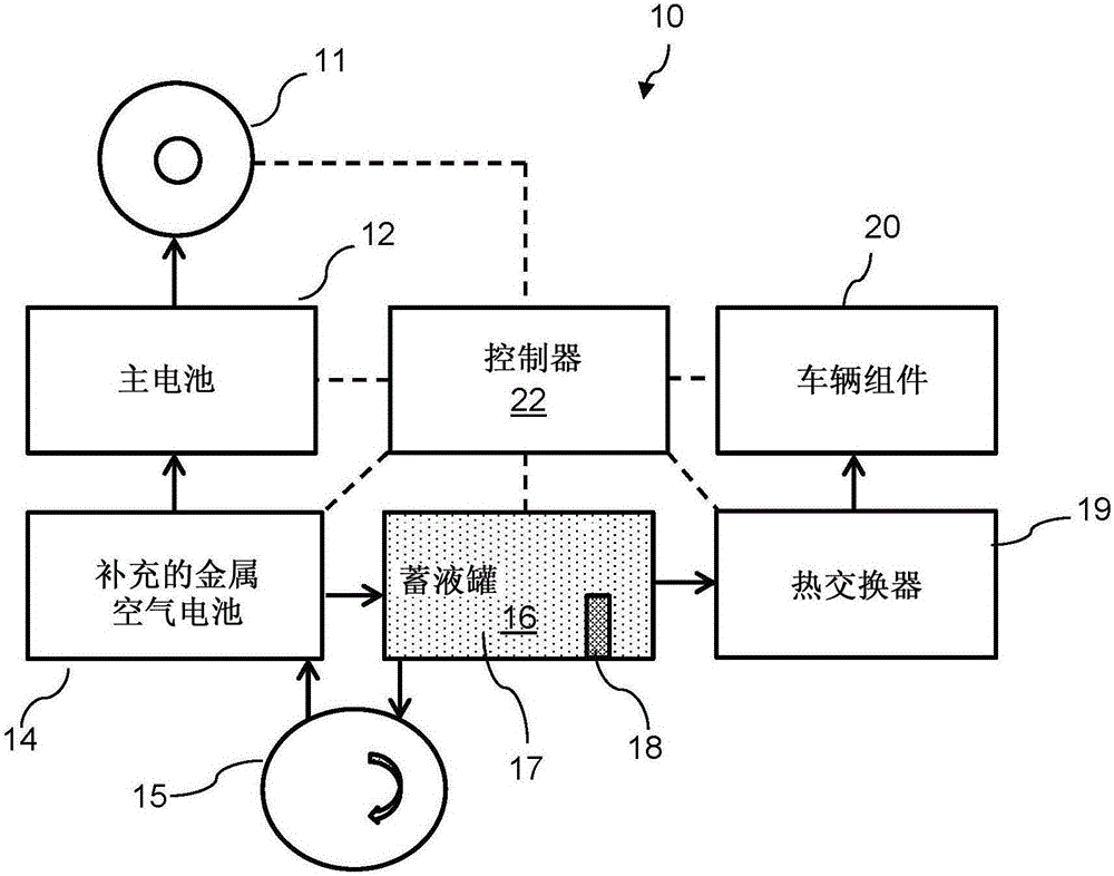
[0016] A known power source for electric vehicles is a lithium battery, which has many benefits. However, the specific cost of a unit of residual energy (eg, kilowatt-hour) stored in a lithium battery is relatively high. Aspects of the invention may relate to a system for extending the range of an electric vehicle (e.g., an electric car) by adding a supplemental metal-air battery that is less expensive than the (existing) rechargeable primary lithium battery. Language has a lower concrete cost per unit of energy.

[0017] When the capacity of ...


PUM


Abstract

A system and a method for heating a componenet of an electric vehicle may be particularly beneficial in cold weather places and / or during winter time. The vehicle may be primarily powered by a main battery. The system may include a supplementary battery being metal-air battery including an electrolyte, for extending the driving range of the electric vehicle and a reservoir tank for holding an electrolyte volume for the metal-air battery, the electrolyte may be heated to a desired temperature. The system may further include a heat exchanger for conveying heat from the electrolyte volume, said heat is conveyable to said passenger's cabin.

Description

Background technique [0001] Using a conventional air conditioning system to heat an electric vehicle, especially in colder locations, consumes a large amount of electricity stored in the vehicle's main battery, thus potentially reducing the vehicle's driving range. In vehicles powered by internal combustion engines, the heat generated during combustion is used to heat other components of the vehicle, such as the passenger cabin or driver's seat. This option of using excess heat energy from the vehicle's engine does not exist in electric vehicles. [0002] Metal-air cells are known in the art. Such a metal-air cell or battery includes a metal anode including, for example, aluminum, zinc, lithium, beryllium, calcium, etc.; and a gas diffusion cathode. The chemical reaction that generates electricity in a battery is the oxidation of the metal anode in either an aqueous or non-aqueous electrolyte. The electrolyte is used to transport ions between the cathode and anode. In some...

Claims


Application Information

Patent Timeline
Patent Type & Authority Applications(China)
IPC IPC(8): H01M12/06B60L11/18B60H1/22B60N2/56H01M10/615H02J7/32F28D1/06H05B3/00
CPCH01M12/06H01M10/615B60L2240/34B60L2240/545B60L2260/56B60L2270/44F28D15/00F28D20/0034F28D2021/0028F28D2021/008Y02T10/7072Y02T90/14H01M6/5077H01M2220/20H01M10/657B60H1/143H01M10/625B60L53/80B60L58/18B60L58/21B60L58/27B60L50/64B60N2/5685H01M6/50H01M16/00Y02E60/14B60L3/10B60L3/104B60L3/106B60L3/12B60L9/16B60L7/10Y02T10/70B60L53/14B60Y2200/91B60L58/12H01M6/5038B60N2/56H02J7/342Y02T90/12H01M10/44H01M10/46
Inventor 阿维夫·齐东阿夫拉汉姆·亚德加尔
Owner PHINERGY
Why Eureka
Try Eureka