
Vesicle Structure and Multilayer Vesicle System

A technology of capsules and composites, which is applied in the field of manufacturing composite resin parts, and can solve problems such as fiber lengths being laid

Active Publication Date: 2021-02-12
THE BOEING CO
View PDF4 Cites 0 Cited by
  • Summary
  • Abstract
  • Description
  • Claims
  • Application Information

AI Technical Summary

Problems solved by technology

Furthermore, because the bladder is flexible during layup operations, this is especially useful for automatic filament laying, especially when the orientation dictates that the ply must be laid in a direction perpendicular to the bladder. (Automated Fiber Placement, automatic fiber placement) machine operation can be a manufacturing challenge: that is, the situation that may result in excessive fiber length being laid

Method used


Image

  • Vesicle Structure and Multilayer Vesicle System
  • Vesicle Structure and Multilayer Vesicle System
  • Vesicle Structure and Multilayer Vesicle System

Examples


Embodiment Construction

[0087] The disclosed arrangements will now be described more fully hereinafter with reference to the accompanying drawings, in which some, but not all, of the disclosed arrangements are shown. In fact, a number of different arrangements may be provided and should not be construed as limited to the arrangements set forth herein. Rather, these arrangements are arranged so that this disclosure will be thorough and complete, and will fully convey the scope of the disclosure to those skilled in the art.

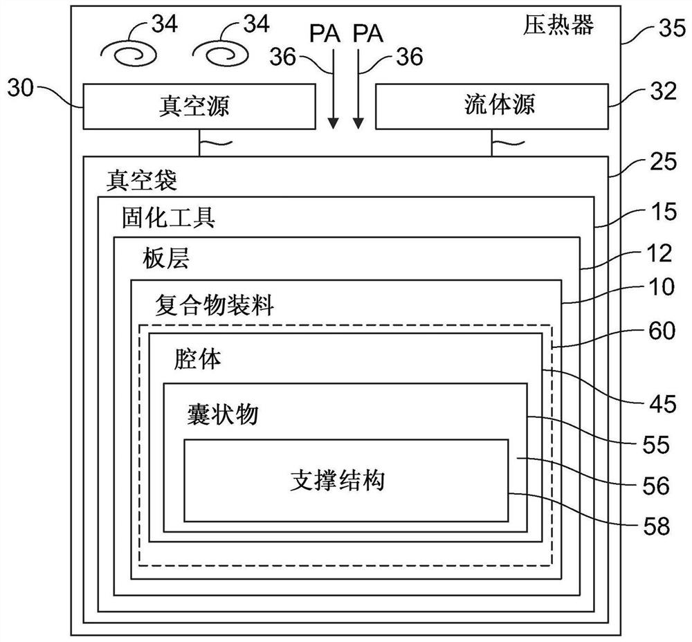
[0088] first reference figure 1 , the uncured composite resin part 10 may hereinafter be referred to as "charge (filler, filling portion, charge)", "composite charge", "composite part charge" or "stringer charge" . This charge can be supported in an autoclave. In particular, charge 10 may be cured on curing tool 15 placed in autoclave 35 where autoclave heat 34 and pressure 36 are applied to composite charge 10 . The composite charge 10 includes one or more internal voids, con...


PUM

PropertyMeasurementUnit
thicknessaaaaaaaaaa

Abstract

The invention discloses a bladder structure and a multilayer bladder system, the bladder structure comprising a plurality of walls defining a bladder cavity comprising an initial cross-sectional dimension. A first plurality of corrugated features is disposed along at least one of the plurality of walls defining the bladder cavity. In one arrangement, after the structure becomes expanded during curing of the composite charge, the first plurality of corrugated features allows the structure to expand from an initial cross-sectional dimension to a second cross-sectional dimension greater than Initial cross section size.

Description

technical field [0001] The present disclosure relates generally to methods and apparatus for manufacturing composite resin parts, and generally to bladder (bladder) systems for use in curing composite parts. Background technique [0002] Composite resin parts may be cured in an autoclave (autoclave), which applies heat and pressure to the composite part during the curing cycle. Some part geometries include internal cavities that can cause composite parts to collapse under autoclave pressure unless tools such as inflatable (inflatable) bladders are placed in the composite in the cavity of the component. This expandable bladder can expand during the curing process to react to the autoclave pressure applied to the composite part. Typically, these inflatable bladders are pressurized by venting them with a vacuum bag. [0003] There are several problems with vented bladders that often lead to inconsistencies in the part being cured. For example, failure to properly vent the b...

Claims


Application Information

Patent Timeline
Patent Type & Authority Patents(China)
IPC IPC(8): B29C70/44B29C70/54
CPCB29C70/446B29C70/54B29C33/505B29C70/342B29C70/544B29C49/28
Inventor 埃米·伊丽莎白·巴赫梅甘·E·布利斯威廉·霍伦斯坦纳威廉·亨利·英格拉姆约翰·登普西·莫里斯乔纳森·圣地亚哥本杰明·杰弗里·斯蒂芬森塞谬尔·雷·斯图尔特查尔斯·威廉·托马斯
Owner THE BOEING CO
Learn More