Clothes display device using ball screw push and pull

A ball screw and display device technology, applied in the field of display stands, can solve the problems of affecting sales, reducing economic benefits, and high rent, and achieving the effects of increasing purchase desire, increasing economic benefits, and improving utilization rates

Active Publication Date: 2019-12-13
QINZHOU UNIV
View PDF6 Cites 0 Cited by
  • Summary
  • Abstract
  • Description
  • Claims
  • Application Information

AI Technical Summary

Problems solved by technology

The spiral clothing display rack displays clothes from top to bottom, avoiding the accumulation of clothes when customers choose them, and the clothes hang up and down, which has a sense of hierarchy, but there are still the following disadvantages: First, the clothes are vertically hung up and down along the column, and the adjacent clothes There will be a part of the length overlap between them. If the clothes with a relatively long length are hung, the clothes below will be covered or the clothes below will be covered, so that the display effect will not be achieved. It is only suitable for displaying clothes with a short length, and the scope of use is limited. Poor practicability; second, the clothes are hung up and down. If the clothes are hung densely, the adjacent clothes overlap each other, which will affect the display effect and reduce the customer's desire to buy. If the clothes are hung sparsely, the amount of clothes hanging on the entire column will be less. The rent of shopping malls and clothing stores is relatively high, which reduces economic benefits; third, the clothes hanging at the bottom are relatively low, requiring customers to bow their heads or bend over to see the clothes, which does not achieve the display effect, and the base is located at Under the clothes, customers' feet or legs are likely to touch the base when they choose clothes, which will reduce customers' desire to buy and affect sales

Method used


Image

  • Clothes display device using ball screw push and pull

Examples


Embodiment Construction

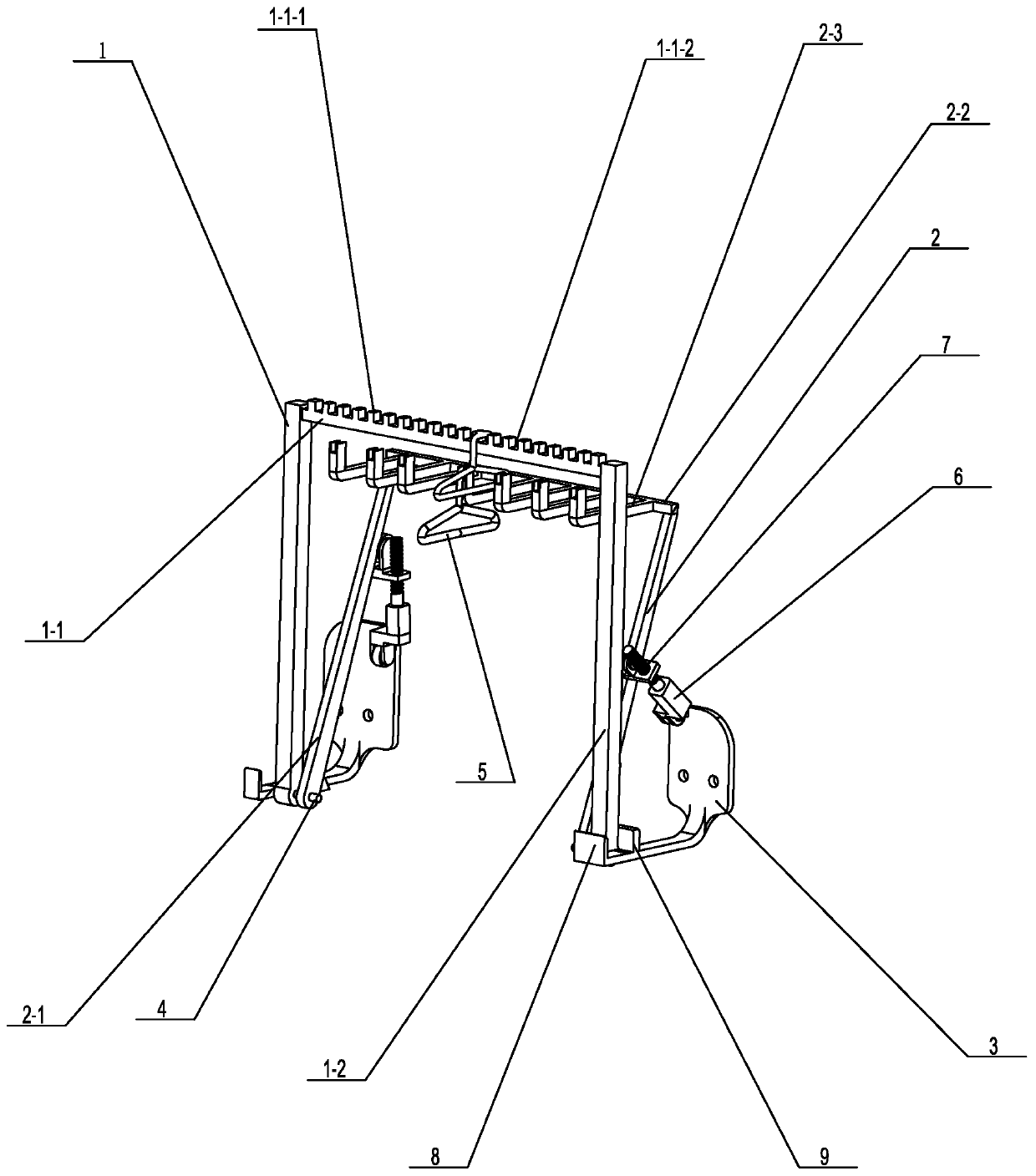
[0020] Such as figure 1 As shown, a specific embodiment of the present invention is proposed. A clothing display device that adopts ball screw push-pull includes an upper display rack 1 and a lower display rack 2. The upper display rack 1 includes an upper display rod 1-1 arranged horizontally. The above-mentioned display rod 1-1 is provided with a plurality of spacing bosses 1-1-1 with intervals between adjacent ones, and a placeable The clothes hanger groove 1-1-2 of the clothes hanger 5 prevents the clothes hanger 5 from sliding along with the movement of the upper display rod 1-1 back and forth, and the lower ends of the upper display rod 1-1 are connected with vertically arranged upper display supports Rod 1-2, both display support rods 1-2 are equipped with mounting frame 3 that can be fixed on the fixture, and mounting frame 3 can be installed on a wall, a column or a large stable object, and the present embodiment sets mounting frame 3 It is a square plate frame, and ...


PUM


Abstract

The invention discloses a clothes display device adopting a ballscrew to push and pull. The clothes display device comprises upper and lower display racks. An upper exhibition rack comprises an upper display rod with multiple limiting bosses, and upper display support rods arranged on two ends of the upper display rod. Two upper support rods are provided with installing racks fixed on fixed objects. A lower display rack comprises two lower support rods, and a lower display rod with multiple clothes hangers. The two installing racks are connected with double-acting air cylinders connected to one upper display support rod and connected to a lower display support rods. The display rack comprises upper and lower layers of display racks so that many clothes of all sizes can be hung. By the ballscrew connected to a driving unit, the upper and lower display racks can be mechanically staggered so that good display effect is obtained and the rack looks attractive and a customer can see clearly all display clothes. Conflicts are avoided and buy desire is improved. The clothes display device is worthy of broad promotion by improving economic benefit.

Description

technical field [0001] The invention relates to a display rack, in particular to a clothing display device which is pushed and pulled by a ball screw. Background technique [0002] Clothing display devices are widely used in shopping malls and clothing stores. In order to attract customers, highlight styles, and establish brands, various businesses pay more and more attention to store design. From the overall style, to furniture matching, and even to the placement of goods, all have gone through Well-designed. However, the existing common clothing display stand has a single style, usually comprising a clothes shaft made of a round rod, two bases, and a support frame. One body, the bottom ends of the support frame are respectively fixedly connected with the base, and the base is generally equipped with rollers. Although the clothing display rack with this structure is easy to move and carry, it is easy for the customer to make the clothing display rack slide when picking cl...

Claims


Application Information

Patent Timeline
Patent Type & Authority Patents(China)
IPC IPC(8): A47F7/24A47F5/00
CPCA47F5/0043A47F5/0093A47F7/24
Inventor 崔传真何维黄红生杨永杰蒋子庆鲁娟袁雪鹏孙腾王跃飞
Owner QINZHOU UNIV
Why Eureka
Try Eureka