A kind of bending machine

A workbench and fastening frame technology, applied in metal processing equipment, feeding devices, positioning devices, etc., can solve the problems of less bending machines for folding steel bars, waste of labor and energy, inconvenient maintenance, etc. Stable, low cost and stable structure

Active Publication Date: 2018-03-23
DONGTAI CITY HUAWEI STANDARD COMPONENT CO LTD
View PDF7 Cites 0 Cited by
  • Summary
  • Abstract
  • Description
  • Claims
  • Application Information

AI Technical Summary

Problems solved by technology

[0002] Existing U-bending machines are generally used for bending tubes and thin plates, and there are relatively few U-bending machines for bending steel bars.
At the same time, the U-bending machines in the prior art are usually large in size, high in cost, and inconvenient to maintain; while the existing small U-bending machines are time-consuming and labor-intensive to use, wasting manpower and energy

Method used


Image

  • A kind of bending machine
  • A kind of bending machine
  • A kind of bending machine

Examples


Embodiment Construction

[0027] In order to deepen the understanding of the present invention, the present invention will be described in further detail below in conjunction with the examples and accompanying drawings. These examples are only used to explain the present invention, and do not constitute a limitation to the protection scope of the present invention.

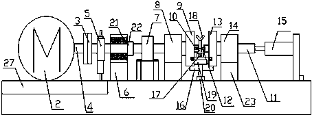
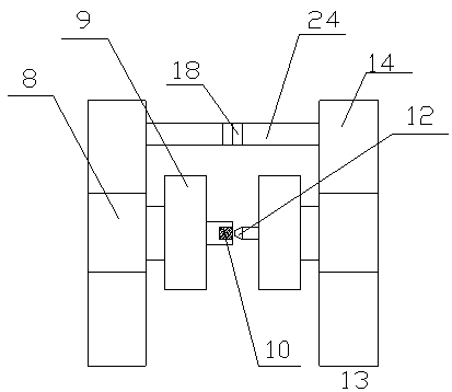
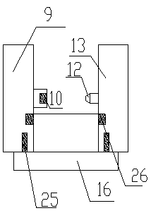
[0028] Such as Figure 1-4 Shown: a U bending machine, including a workbench 1, a motor 2 is provided on the left edge of the workbench 1, the motor 2 is connected to a chuck 3, a rotating shaft 4 is arranged inside the chuck 3, and a reinforcing frame 5 is arranged on the rotating shaft 4 , the right side of the reinforcing frame 5 is provided with a first fastening frame 6, the right side of the first fastening frame 6 is provided with a toothed plate 7, the right side of the toothed plate 7 is provided with a second fastening frame 8, and the second fastening frame 8 is connected with The left fixed disk 9 links to each other, the end o...


PUM


Abstract

The invention discloses a U bending machine which comprises a workbench; the left edge of the workbench is equipped with a motor; the motor is connected with a chuck; a rotary shaft is arranged in the chuck; a reinforcing frame is arranged on the rotary shaft; a first fastening frame is arranged at the right side of the reinforcing frame; a tooth disc is arranged at the right side of the first fastening frame; a second fastening frame is arranged at the right side of the tooth disc; the second fastening frame is connected with a left fixed disc; a shaft sleeve is mounted at the tail end of the rotary shaft; a hole is formed in the center of the shaft sleeve; a telescopic pole, which is as high as the rotary shaft, is arranged on the right side of the rotary shaft; a tapered sleeve is mounted at the top end of the left side of the telescopic pole; a right fixed disc is arranged on the telescopic pole; the right fixed disc is connected with a third fastening frame; the tail end of the right side of the telescopic pole is connected with an air cylinder; a baffle plate is mounted on the left fixed disc and the right fixed disc; a roller slot is formed in the baffle plate; a Y-shaped supporting frame is arranged behind the baffle plate; a T-shaped bracket is arranged on the workbench in front of the baffle plate; and a supporting device is arranged in front of the T-shaped bracket. The U bending machine has the advantages of being simple in structure, low in cost and convenient to mount and dismount, and is suitable for being popularized.

Description

technical field [0001] The invention relates to a U bending machine. Background technique [0002] Existing U-bending machines are generally used for bending pipes and thin plates, and there are relatively few U-bending machines for bending steel bars. At the same time, the U-bending machines in the prior art are usually large in size, high in cost, and inconvenient to maintain; while the existing small U-bending machines are time-consuming and laborious to use, wasting manpower and energy. Contents of the invention [0003] The purpose of the present invention is to overcome the above disadvantages and provide a U bending machine with simple structure, low cost, convenient installation and disassembly, easy maintenance and suitable for popularization. [0004] The present invention is realized through the following technical solutions: a U-bending machine, including a workbench, a motor is provided on the left edge of the workbench, the motor is connected to a chuck, a r...

Claims


Application Information

Patent Timeline
Patent Type & Authority Patents(China)
IPC IPC(8): B21D7/00B21D43/00
CPCB21D7/00B21D43/003
Inventor 刘付林
Owner DONGTAI CITY HUAWEI STANDARD COMPONENT CO LTD
Why Eureka
Try Eureka