
Rigidity and viscosity combined restraint structure and method

A restraint structure and rigid restraint technology, applied to bridge parts, bridges, buildings, etc., can solve the problem of large beam end displacement, increasing the difficulty of designing and manufacturing railway beam end expansion devices, affecting the comfort and safety of railway trains, etc. problems, to achieve the effects of reducing tower root bending moment and displacement along the bridge, improving static and dynamic performance, and improving safety and comfort

Active Publication Date: 2016-12-07
CHINA MAJOR BRIDGE ENERGINEERING
View PDF4 Cites 0 Cited by
  • Summary
  • Abstract
  • Description
  • Claims
  • Application Information

AI Technical Summary

Problems solved by technology

At present, the design of long-span high-speed railway cable-stayed bridges often adopts a free-moving system along the bridge direction. This type of constraint can reduce the impact of temperature changes and impact loads such as earthquakes and train operations on the bridge. However, the beam end displacement caused by impact loads is usually Therefore, it not only increases the difficulty of the design and manufacture of the railway beam end expansion device, but also affects the comfort and safety of railway train operation

Method used


Image

  • Rigidity and viscosity combined restraint structure and method

Examples


Embodiment Construction

[0020] The present invention will be described in further detail below in conjunction with the accompanying drawings and embodiments.

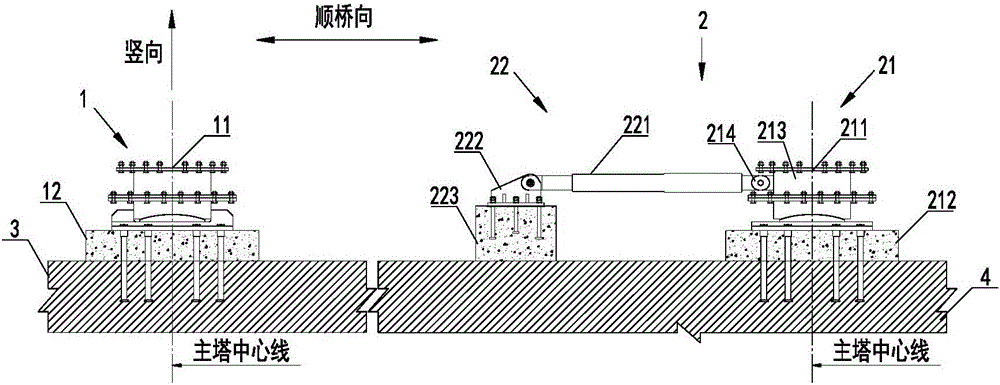
[0021] Such as figure 1 As shown, a rigid and viscous combined restraint structure is used for the restraint system of the cable-stayed bridge. The cable-stayed bridge includes the first main tower 3 and the second main tower 4. The rigid and viscous combined restraint structure includes respectively The rigid restraint device 1 and the combined restraint device 2 supporting both ends of the cable-stayed bridge.

[0022] The rigid restraint device 1 includes a rigid support 11 and a rigid base 12 , the rigid support 11 is set above the rigid base 12 , and the rigid base 12 is set on the first main tower 3 and located on the center line of the first main tower 3 .

[0023] The combined restraint device 2 comprises a vertical restraint device 21 and a viscous restraint device 22, the vertical restraint device 21 comprises a vertical support 211...


PUM


Abstract

The invention discloses a rigidity and viscosity combined restraint structure and method, which are applied to a restraint system of a cable-stayed bridge. The cable-stayed bridge comprises a first main tower and a second main tower. The rigidity and viscosity combined restraint structure comprises a rigid restraint device supporting one end of the cable-stayed bridge and a combined restraint device supporting the other end of the cable-stayed bridge, wherein the rigid restraint device comprises a rigid support and a rigid substrate; the rigid support is arranged above the rigid substrate, and the rigid substrate is arranged on the first main tower; the combined restraint device comprises a vertical restraint device and a viscosity restraint device, wherein the vertical restraint device comprises a vertical support and a vertical substrate; the vertical support is arranged above the vertical substrate, and the vertical substrate is arranged on the second main tower; the viscosity restraint device comprises a viscosity restraint substrate arranged on the second main tower; a fixing component is arranged on the viscosity restraint substrate; a moving component is also connected between the vertical restraint device and the fixing component; and the moving component is arranged in the axle direction. Through the adoption of the rigidity and viscosity combined restraint structure and method disclosed by the invention, the static and dynamic performance of a bridge can be improved, the operation safety and comfort of trains can be guaranteed, and the design and construction economy of the bridge is increased.

Description

technical field [0001] The invention relates to the field of bridge construction, in particular to a rigid and viscous combined restraint structure and method. Background technique [0002] The restraint system of long-span high-speed railway cable-stayed bridges affects the transmission and distribution of internal forces between the structural components of the cable-stayed bridge. Among them, whether the restraint system along the bridge direction is reasonable not only has a significant impact on the dynamic performance of the cable-stayed bridge, such as wind resistance and earthquake resistance, but also And it is an important factor to determine the safety and comfort of high-speed railway train operation. At present, the design of long-span high-speed railway cable-stayed bridges often adopts a free-moving system along the bridge direction. This type of constraint can reduce the impact of temperature changes and impact loads such as earthquakes and train operations o...

Claims


Application Information

Patent Timeline
IPC IPC(8): E01D19/00E01D19/04
CPCE01D19/00E01D19/04
Inventor 罗扣梅大鹏徐科英肖海珠高宗余徐伟陈翔付岚岚李奇
Owner CHINA MAJOR BRIDGE ENERGINEERING
Learn More