
Permanent magnet motor controller used for electrolytic capacitor-free motor drive system and method

A motor drive system and electrolytic capacitor technology, applied in motor generator control, electronic commutation motor control, AC motor control, etc., can solve the problems of DC bus voltage fluctuation and small capacitance value, and achieve stable output and suppress fluctuation. , the effect of reducing the volatility coefficient

Active Publication Date: 2017-08-04
JIANGSU UNIV
View PDF3 Cites 10 Cited by
  • Summary
  • Abstract
  • Description
  • Claims
  • Application Information

AI Technical Summary

Problems solved by technology

[0003] The purpose of the present invention is to solve the problems existing in the existing electrolytic capacitor drive system, and propose a permanent magnet motor controller for the electrolytic capacitor motor drive system to solve the problem in the electrolytic capacitor drive system with the control method of the controller. The contradiction between the small capacitor value and the fluctuation of the DC bus voltage and improve the power factor of the input side of the system, and improve the static and dynamic performance of the motor on this basis

Method used


Image

  • Permanent magnet motor controller used for electrolytic capacitor-free motor drive system and method
  • Permanent magnet motor controller used for electrolytic capacitor-free motor drive system and method
  • Permanent magnet motor controller used for electrolytic capacitor-free motor drive system and method

Examples


Embodiment Construction

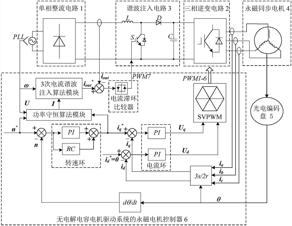
[0020] see figure 2 , The motor drive system without electrolytic capacitors is composed of a single-phase rectifier circuit 1, a harmonic injection circuit 3 and a three-phase inverter circuit 2 connected in series in sequence, and the three-phase inverter circuit 2 drives the permanent magnet synchronous motor 4. The output terminals of the permanent magnet motor controller 6 used in the electrolytic capacitor motor drive system according to the present invention are respectively connected to the harmonic injection circuit 3 and the three-phase inverter circuit 2 of the electrolytic capacitor motor drive system. The permanent magnet motor controller 6 is composed of the third-order current harmonic injection algorithm module, power conservation algorithm module, current hysteresis comparator, speed loop, current loop, 3s / 2r coordinate transformation module, dθ / dt calculation module and SVPWM modulation module .

[0021] The rotor position angle θ of the permanent magnet sy...


PUM


Abstract

The invention discloses a permanent magnet motor controller used for an electrolytic capacitor-free motor drive system and a method. Harmonic currents are injected to the electrolytic capacitor-free motor drive system for three times, the input side power pulsating quantity of the electrolytic capacitor-free motor drive system is reduced, decoupling of an electrolytic capacitor-free motor drive system input side control objective and a motor side control objective is realized, the problem that original power of a system is unbalanced is solved, the electrolytic capacitor-free motor drive system can obtain a high input power factor approximate to 1, thereby effectively suppressing fluctuation of a bus capacitor voltage, reducing a fluctuation coefficient of a DC bus voltage, and providing conditions for high-performance operation of a motor; and repetitive control is introduced into a speed loop of vector control, a rotation speed loop of the motor is improved, and on this basis, an SVPWM modulation module is utilized to generate six paths of instructions to control motor operation, thereby effectively solving the problem of poor output accuracy under a bus voltage fluctuation working condition, and realizing rapid and stable output of the controller.

Description

technical field [0001] The invention belongs to the technical field of motor control, in particular to the control technology of a non-electrolytic capacitor motor drive system. Background technique [0002] Permanent magnet synchronous motors have the advantages of simple structure, high power density, and convenient maintenance. They have gradually replaced DC motors and asynchronous motors in the fields of household appliances, industrial production, and automobile drives. The drive system used in this type of motor generally adopts a voltage source inverter. This voltage source inverter uses a large-capacity electrolytic capacitor to absorb and release a large amount of energy to maintain a stable DC bus voltage and provide a high-performance motor for high-performance operation. condition. However, large-capacity electrolytic capacitors have shortcomings such as short life and poor thermal stability. The life of large-capacity electrolytic capacitors is generally 8000h...

Claims


Application Information

Patent Timeline
Patent Type & Authority Applications(China)
IPC IPC(8): H02P21/00H02P21/22H02P27/12
CPCH02P21/00H02P27/12
Inventor 张超徐浩胡鑫朱孝勇全力杜怿
Owner JIANGSU UNIV
Learn More