Single-stage step-up inverter

A booster and inverter technology, applied in the field of single-stage booster inverters, can solve the problems of high cost and poor output effect, and achieve high power factor, reduced circuit cost, and good output effect. Effect

Inactive Publication Date: 2015-11-25
LG ELECTRONICS CHINA RANDD CENT SHANGHAI CO LTD
View PDF5 Cites 4 Cited by
  • Summary
  • Abstract
  • Description
  • Claims
  • Application Information

AI Technical Summary

Problems solved by technology

[0005] Aiming at the deficiencies of the above two boost inverters, the present invention proposes a single-stage boost inverter formed by cascading a rectifier circuit, a π-type circuit and an inverter circuit, which overcomes the problems of the prior art The problem of high cost and poor output effect

Method used


Image

  • Single-stage step-up inverter
  • Single-stage step-up inverter
  • Single-stage step-up inverter

Examples


Embodiment Construction

[0019] The technical means adopted by the present invention to achieve the intended invention purpose are further described below in conjunction with the drawings and preferred embodiments of the present invention.

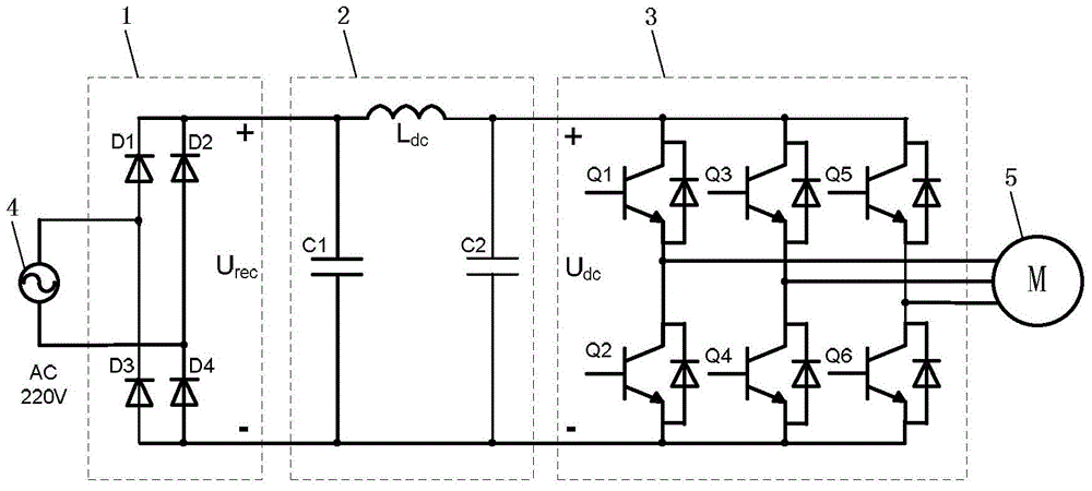
[0020] image 3 It is a circuit diagram of a single-stage boost inverter according to an embodiment of the present invention. Such as image 3 As shown, the circuit includes: input rectification circuit 1, π-type circuit 2 and inverter circuit 3; input rectification circuit 1 is connected to external AC power 4, π-type circuit 2 is connected to input rectification circuit 1 and inverter circuit 3, and inverter circuit 3 is connected to an external load 5; wherein,

[0021] The π-type circuit 2 includes: a first capacitor C1, a second capacitor C2 and an inductor L dc ; The first capacitor C1 is connected in parallel with the second capacitor C2, and the inductance L dc Connected to the parallel circuit of the first capacitor C1 and the second capacitor C2;

...


PUM


Abstract

The invention discloses a single-stage step-up inverter, which comprises an input rectification circuit, a pi-type circuit and an inverter circuit, wherein the input rectification circuit is connected with external AC; the pi-type circuit is connected with the input rectification circuit and the inverter circuit, and the inverter circuit is connected with an external load; the pi-type circuit comprises a first capacitor, a second capacitor and an inductor; the first capacitor and the second capacitor are in parallel connection; the inductor is connected onto a parallel loop of the first capacitor and the second capacitor; the first capacitor is in parallel connection with the input rectification circuit; the second capacitor is in parallel connection with the inverter circuit; the input rectification circuit is used for rectifying the external AC into DC pulsating voltage; when the DC pulsating voltage is higher than a voltage limit value, the pi-type circuit is used for DC filter; and when the DC pulsating voltage is lower than the voltage limit value, part of or all of bridge arms in the inverter circuit are adjusted to be in a shoot-through state, and the inductor in the pi-type circuit is charged, and after the shoot-through state is over, inductive voltage generated by the inductor is overlapped with the DC pulsating voltage and then outputted to the inverter circuit.

Description

technical field [0001] The invention relates to a motor drive circuit, in particular to a novel single-stage step-up inverter, which can be used to drive motor loads. Background technique [0002] In the motor drive circuit of the prior art, the inverter circuit used mainly has the following two methods: as figure 1 As shown, the first method adopts a two-stage structure. The front stage uses a boost circuit to boost the DC voltage, and realizes high power factor and low harmonic current on the input power side. Decoupling of input and output. [0003] Such as figure 2 As shown, another method uses a small-capacity capacitor on the DC side. The DC voltage fluctuates with the input voltage, and the output power and torque also fluctuate with the input voltage. This method uses a power tracking method to make the output power fluctuate with the input voltage. . [0004] The first method can obtain better input and output effects, but the circuit cost is increased by adopt...

Claims


Application Information

Patent Timeline
Patent Type & Authority Applications(China)
IPC IPC(8): H02M5/44
Inventor 庄凯
Owner LG ELECTRONICS CHINA RANDD CENT SHANGHAI CO LTD
Why Eureka
Try Eureka