Electrolytic-free capacitor power converter and control method for permanent magnet synchronous motor drive system

A permanent magnet synchronous motor and power converter technology, applied in motor control, motor generator control, AC motor control and other directions, can solve the problems of DC bus voltage fluctuation, poor static and dynamic performance of the motor, and achieve high input power factor, The effect of high power factor and high efficiency

Active Publication Date: 2018-12-21
JIANGSU UNIV
View PDF9 Cites 4 Cited by
  • Summary
  • Abstract
  • Description
  • Claims
  • Application Information

AI Technical Summary

Problems solved by technology

[0004] The purpose of the present invention is to provide a non-electrolytic capacitor power converter for permanent magnet synchronous motors and its control method, which can effectively suppress the fluctuation of the DC bus voltage and have high input power factor,

Method used


Image

  • Electrolytic-free capacitor power converter and control method for permanent magnet synchronous motor drive system
  • Electrolytic-free capacitor power converter and control method for permanent magnet synchronous motor drive system
  • Electrolytic-free capacitor power converter and control method for permanent magnet synchronous motor drive system

Examples


Embodiment Construction

[0026] The embodiments described below by referring to the figures are exemplary only for explaining the present invention and should not be construed as limiting the present invention.

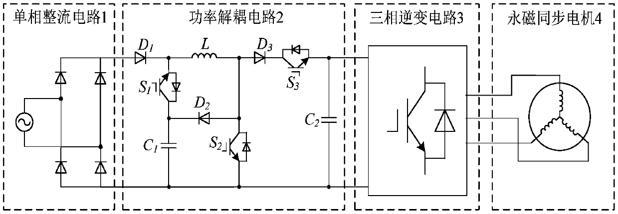
[0027] Such as figure 1 As shown, the non-electrolytic capacitor power converter for the permanent magnet synchronous motor drive system proposed by the present invention is composed of a single-phase rectifier circuit 1, a power decoupling circuit 2 and a three-phase inverter circuit 3 connected in series in sequence. The input end of the single-phase rectification circuit 1 is connected to the grid, the positive pole of the output end of the single-phase rectification circuit 1 is connected to the positive pole of the power decoupling circuit 2, the negative pole of the output end of the single-phase rectification circuit 1 is connected to the negative pole of the power decoupling circuit 2 and the three-phase The negative poles of the inverter circuit 3 are connected. The positive pole of...


PUM

PropertyMeasurementUnit
Capacitanceaaaaaaaaaa

Abstract

A non-electrolytic capacitor power converter and control method for driving system of permanent magnet synchronous motor are disclosed, An output positive electrode of the single-phase rectifier circuit is connected with an anode of the first diode, an output negative electrode is connected with a negative electrode of the first thin film capacitor, a second switch tube emitter, a second thin filmcapacitor negative electrode, an input negative electrode of the three-phase inverter circuit, and an emitter of the first switch tube is connected with an inductance terminal and a cathode of the first diode. A collector of the first switch tube and a positive electrode of the first thin film capacitor, second diode cathode connection, A collector of the second switch tube is connected to the other end of the inductor L, simultaneously connected to the anode of the second diode and the anode of the third diode, The cathode of the third diode is connected with the collector of the third switch tube, and the emitter of the third switch tube is connected with the cathode of the second film capacitor, and is connected with the input cathode of the three-phase inverter circuit, which can effectively solve the problems of serious DC bus voltage fluctuation and poor static and dynamic performance of the existing electrolytic capacitance motor drive system.

Description

technical field [0001] The invention belongs to the technical field of power electronic control, and in particular relates to an electrolytic capacitor power converter and a control method for a permanent magnet synchronous motor drive system. Background technique [0002] The permanent magnet synchronous motor (Permanent Magnetic Synchronous Machine, PMSM) has the advantages of simple structure, high power density, and convenient maintenance. It has gradually replaced DC motors and asynchronous motors in industrial applications, household appliances, and automobile drives. This type of motor drive system requires large-capacity electrolytic capacitors to maintain the stability of the DC bus voltage and provide working conditions for the high-performance operation of the motor. However, electrolytic capacitors have disadvantages such as short life, low reliability, and poor thermal stability, which are the main cause of failure in motor drive systems. In order to improve th...

Claims


Application Information

Patent Timeline
IPC IPC(8): H02P25/022H02P25/16H02P29/50H02M5/42
CPCH02M5/42H02P25/16H02P2201/07H02P2207/05H02P25/024H02P29/50H02M1/0038
Inventor 张超胡鑫段璐瑶朱孝勇全力杜怿
Owner JIANGSU UNIV
Why Eureka
Try Eureka