
Power supply for an LED illumination device

a technology of led illumination and power supply, which is applied in the direction of instruments, light sources, electroluminescent light sources, etc., can solve the problems of inability to achieve the effect of reducing and affecting the operation of the ac power source. , to achieve the effect of improving the input power factor of the ac power source, efficient driving, and stable curren

Inactive Publication Date: 2013-07-16
PANASONIC CORP
View PDF4 Cites 4 Cited by
  • Summary
  • Abstract
  • Description
  • Claims
  • Application Information

AI Technical Summary

Benefits of technology

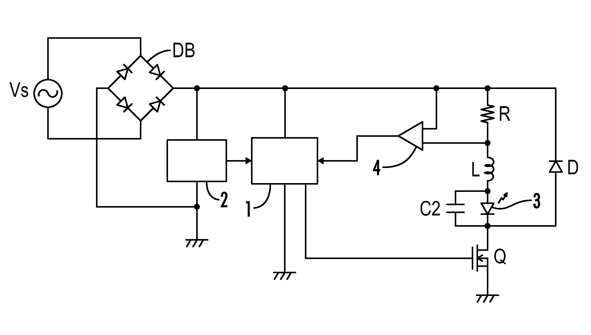
[0014]In consideration of these matters, an object of the present invention is to provide a compact and inexpensive power supply which can improve the input power factor of the AC power source so as to practically and efficiently drive a one or more LEDs with a stable current.
[0016]Because the Class C harmonic regulation can be cleared by limiting the number of serially connected light-emitting diodes as loads for the step-down chopper circuit, even though the step-down chopper circuit has a lesser ability to improve the input power factor than that of the step-up chopper circuit, no longer needing to provide the step-up chopper circuit in the previous stage of the step-down chopper circuit results in a more compact and inexpensive power supply.
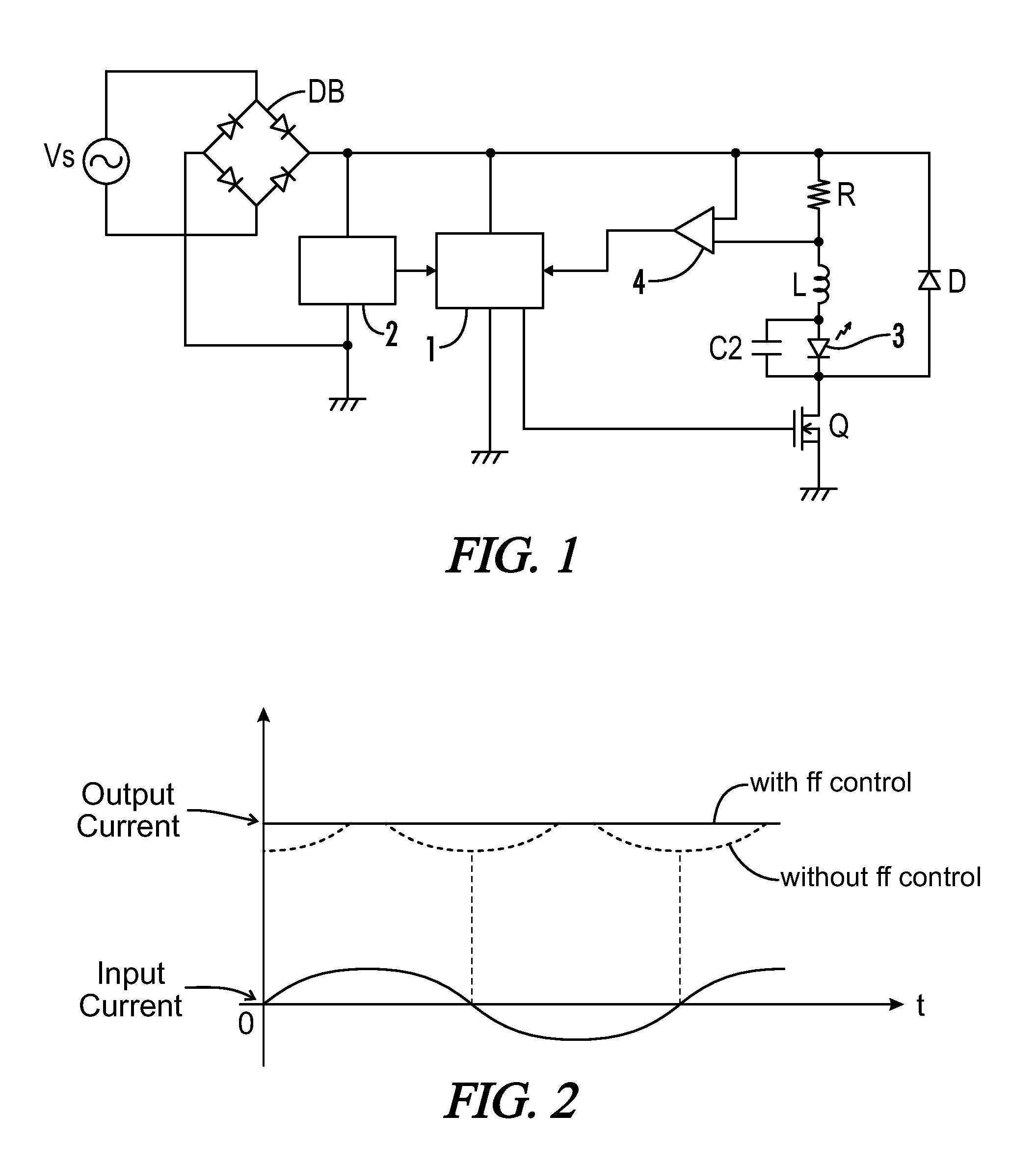
[0019]With regards to the second and third embodiments, because a step-up / step-down chopper circuit or a flyback converter is directly connected to the output terminals of the full-wave rectifier without passing through a smoothing capacitor, and the pulse width of the PWM signal for turning on / off the switching element is forward controlled according to the phase of the pulsating voltage and is feedback controlled according to a current detecting signal of the light-emitting diode, the input power factor from the commercial AC power source can be sufficiently improved without using a step-up chopper circuit. A compact and inexpensive power supply which can efficiently drive one or a small number of light-emitting diodes with a stable current can therefore be realized.
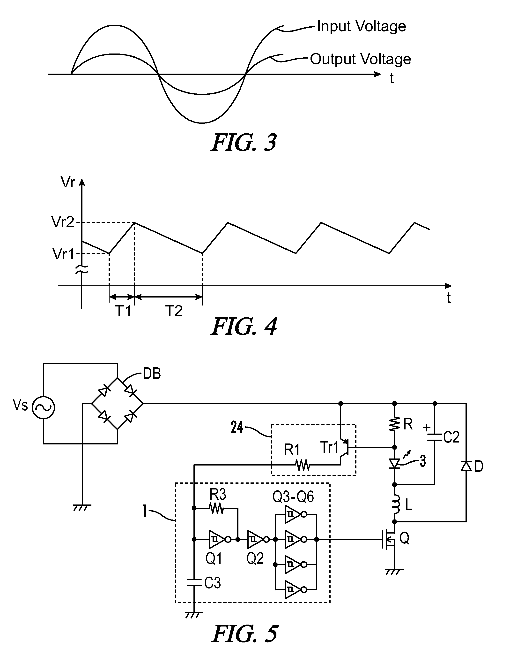
[0020]According to a fourth embodiment of the present invention, and as shown in FIGS. 5 and 8, the control circuit 1 may include a time constant circuit (a capacitor C3 and a resistor R3) for determining the pulse width of the PWM signal, and the phase detection circuit includes a resistor R1 for charging the capacitor C3 of the time constant circuit from the pulsating voltage of the full-wave rectifier DB. Therefore, with a simple configuration the pulse width of the PWM signal can be feed-forward controlled according to the phase of the pulsating voltage.
[0021]According to a fifth embodiment of the present invention, a charging speed of the capacitor C3 of the time constant circuit is made variable by a transistor Tr1 to which the current detected by the current sensor R is applied. Therefore, with a simple configuration the pulse width of the PWM signal can be feedback controlled according to an output current detecting signal.

Problems solved by technology

Even if the power consumed by individual power supplies is small, when a plurality of power supplies with a common structure are connected to the same mains power line in parallel, the effect on other equipment may be considerable.
However, because the pulsating voltage output from the full-wave rectifier DB becomes low in the period when the input voltage from the commercial AC power source Vs is low, current flow to the inductor L is inhibited even when the switching element Q is turned on.
Furthermore, certain operations are undesirably delayed such that even after power is turned off, the light-emitting diode 3 remains lit for a period of time.
Accordingly, the step-up chopper output voltage becomes a DC voltage which is higher than a peak input voltage after full-wave rectification, which is suitable to the case where many light-emitting diodes are serially connected and lit, but is however inefficient in the case where only one or a few light-emitting diodes are lit because power loss increases due to a drop in resistance.
However, because power conversion is performed in two stages, circuit losses such as for example in the switches increase and the circuit configuration becomes overly complex.
However, in the step-down chopper circuit, because a difference between a power source voltage and a load voltage is applied to the inductor upon turning on of the switching element, an input current does not flow in a period when the power source voltage is lower than the load voltage, and an ability to improve an input power factor is limited as compared to the case using the step-up chopper circuit.

Method used


Image

  • Power supply for an LED illumination device
  • Power supply for an LED illumination device
  • Power supply for an LED illumination device

Examples


Embodiment Construction

[0038]Throughout the specification and claims, the following terms take at least the meanings explicitly associated herein, unless the context dictates otherwise. The meanings identified below do not necessarily limit the terms, but merely provide illustrative examples for the terms. The meaning of “a,”“an,” and “the” may include plural references, and the meaning of “in” may include “in” and “on.” The phrase “in one embodiment,” as used herein does not necessarily refer to the same embodiment, although it may. The term “coupled” means at least either a direct electrical connection between the connected items or an indirect connection through one or more passive or active intermediary devices. The term “circuit” means at least either a single component or a multiplicity of components, either active and / or passive, that are coupled together to provide a desired function. The term “signal” means at least one current, voltage, charge, temperature, data or other signal.

[0039]Where eithe...


PUM


Abstract

An illumination device includes one or more LED's and a power supply configured to convert energy from a commercial AC power source and drive said LED's. The power supply includes a rectifier circuit, a phase detection circuit receiving an output voltage from the rectifier circuit and a switching element. A circuit includes the one or more LED's, an inductive element and a diode, and is coupled on a first end to the rectifier circuit and coupled on a second end to ground through the switching element. A current sensor is positioned to detect a current flowing to the light-emitting diode. A control circuit is coupled to receive the detected current and the detected phase of the rectified output voltage, and further coupled to the switching element and configured to generate a PWM signal for driving the switching element at a frequency higher than a commercial AC frequency. The PWM signal has a pulse width determined in accordance with one or more of a feedback control based on a current detected by the current sensor and a feed-forward control based on a phase of the pulsating voltage detected by the phase detection circuit.

Description

[0001]A portion of the disclosure of this patent document contains material that is subject to copyright protection. The copyright owner has no objection to the reproduction of the patent document or the patent disclosure, as it appears in the U.S. Patent and Trademark Office patent file or records, but otherwise reserves all copyright rights whatsoever.CROSS-REFERENCES TO RELATED APPLICATIONS[0002]This application claims benefit of the following patent application(s) which is / are hereby incorporated by reference: Japan Patent Application No. 2009-012412, filed Jan. 22, 2009.STATEMENT REGARDING FEDERALLY SPONSORED RESEARCH OR DEVELOPMENT[0003]Not ApplicableREFERENCE TO SEQUENCE LISTING OR COMPUTER PROGRAM LISTING APPENDIX[0004]Not ApplicableBACKGROUND OF THE INVENTION[0005]The present invention relates generally to power supplies for LED illumination devices. More particularly, the present invention relates to a compact and inexpensive switching power supply with improved power fact...

Claims


Application Information

Patent Timeline
Patent Type & Authority Patents(United States)
IPC IPC(8): H05B37/02
CPCH05B33/0848H05B33/0815H05B45/14H05B45/3725H05B45/375H05B45/38H05B45/385
Inventor KUROKI, YOSHIFUMISHIBATA, SHUNSUKE
Owner PANASONIC CORP
Learn More