
Controllable cabinet door device for electrical cabinet

A technology for electrical cabinets and cabinet doors, which is applied in the direction of electrical components, electrical equipment shells/cabinets/drawers, door/window accessories, etc. The cabinet door is damaged and other problems, and the effect of strong closing force, compact structure and reliable use is achieved.

Inactive Publication Date: 2016-12-07
黄莉
View PDF7 Cites 0 Cited by
  • Summary
  • Abstract
  • Description
  • Claims
  • Application Information

AI Technical Summary

Problems solved by technology

[0003] The existing electrical cabinets all have an operation window, which is opened and closed through an openable cabinet door, and a small lock is usually arranged on the cabinet door to lock with the cabinet body of the electrical cabinet. However, this The locking method is very unsafe. The closing force of the cabinet door of the electrical cabinet is small, and the cabinet door of the electrical cabinet is easily damaged, thereby causing damage to the electronic components in the electrical cabinet. Moreover, the cabinet of the existing electrical cabinet The doors are opened and closed by manual force. For the cabinet doors of some large electrical cabinets, a large driving force is required. Manual force is difficult to operate, and the manual force is small and uneven.

Method used


Image

  • Controllable cabinet door device for electrical cabinet
  • Controllable cabinet door device for electrical cabinet
  • Controllable cabinet door device for electrical cabinet

Examples


Embodiment Construction

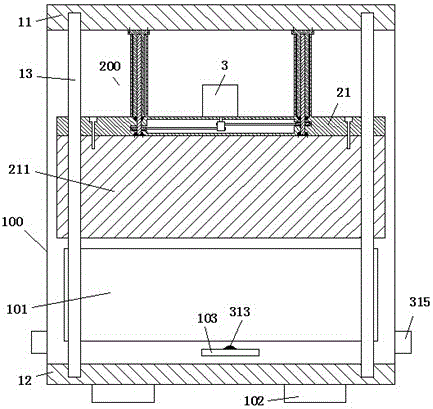
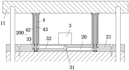
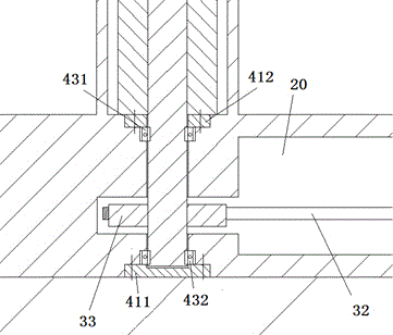
[0010] Combine below Figure 1-3 The present invention will be described in detail.

[0011] A controllable cabinet door device for an electrical cabinet according to an embodiment of the present invention is used to open and close the operation window 101 of the electrical cabinet 100, comprising an upper protrusion 11 integrally provided with the electrical cabinet 100 and The lower protruding part 12, and the two guide columns 13 fixedly arranged between the upper protruding part 11 and the lower protruding part 12 and symmetrically distributed at the front end of the operation window 101, and the two guiding columns 13 The cabinet door panel 211 that is guided by the column 13 and can slide up and down, and the drive assembly 200 used to drive the cabinet door panel 211 to slide up and down, wherein the drive assembly 200 includes left and right symmetrically fixed on the upper protrusion 11 The two fixed sleeve columns 4 on the top, the fixed connection plate 21 that is ...


PUM


Abstract

A controllable cabinet door device for an electrical cabinet is used for carrying out opening and closing on an operation window (101) of the electrical cabinet (100) and comprises an upper protruding portion (11), a lower protruding portion (12), two guide stand columns (13), a cabinet body door plate (211) and a drive assembly (200). The upper protruding portion (11) and the lower protruding portion (12) are integrally arranged with the electrical cabinet (100), the two guide stand columns (13) are fixedly arranged between the upper protruding portion (11) and the lower protruding portion (12) and are symmetrically distributed at the front end of the operation window (101), the cabinet body door plate (211) is guided by the two guide stand columns (13) and can vertically slide, the drive assembly (200) is used for driving the cabinet body door plate (211) to vertically slide, and comprises two fixed sleeve stand columns (4) and a fixed connecting plate (21), the fixed sleeve stand columns (4) are fixed to the upper protruding portion (11) in a left-and-right symmetric manner, and the fixed connecting plate (21) is located below the two fixed sleeve stand columns (4) and fixedly connected with the upper edge of the cabinet body door plate (211).

Description

technical field [0001] The invention relates to the field of electric power, in particular to a controllable cabinet door device for an electric cabinet. Background technique [0002] At present, the electrical cabinet is widely used, and it is mainly used for installing electronic components to protect the normal operation of the electronic components. [0003] The existing electrical cabinets all have an operation window, which is opened and closed through an openable cabinet door, and a small lock is usually arranged on the cabinet door to lock with the cabinet body of the electrical cabinet. However, this The locking method is very unsafe. The closing force of the cabinet door of the electrical cabinet is small, and the cabinet door of the electrical cabinet is easily damaged, thereby causing damage to the electronic components in the electrical cabinet. Moreover, the cabinet of the existing electrical cabinet The doors are all switched by manual force application. For ...

Claims


Application Information

Patent Timeline
IPC IPC(8): E05F15/603E05F15/40H05K5/02
CPCE05F15/603E05F15/40H05K5/0217
Inventor 黄莉
Owner 黄莉
Learn More