Wire outlet structure applied to corrugated lamp

A technology of corrugated lamps and wires, which is applied to the parts of lighting devices, lighting devices, outdoor lighting, etc. It can solve the problems of decreased waterproof effect, poor waterproof performance, loose waterproof wire fixers, etc., and achieves beautiful appearance and good waterproof effect of effect

Inactive Publication Date: 2016-12-07
广东人和照明实业有限公司
View PDF6 Cites 0 Cited by
  • Summary
  • Abstract
  • Description
  • Claims
  • Application Information

AI Technical Summary

Problems solved by technology

[0002] There are generally two types of outlet structures for existing corrugated lights. The first is to lead out the wires from the back of the corrugated lamp, and then install a wire fixer at the outlet to fix the wires. When using this outlet structure, the wires must be wound to the corrugated lamp. The side of the lamp, and then pull it to the ground to connect to the mains. The wires that wind out will make the installation of the corrugated lamp unsightly, and because the outlet is perpendicular to the lamp housing, the waterproof performance is not good; the second is in the corrugated lamp. The wires are led out from the left and right sides, and then waterproof wire fixers are installed at the outlets. This outlet structure can make the installation of corrugated lights beautiful, but with the use of corrugated lights, the waterproof wire fixers are prone to loosening, which leads to the loss of waterproof effect. Decline, so there will be a situation where the corrugated light is burned due to water seepage

Method used


Image

  • Wire outlet structure applied to corrugated lamp
  • Wire outlet structure applied to corrugated lamp
  • Wire outlet structure applied to corrugated lamp

Examples


Embodiment Construction

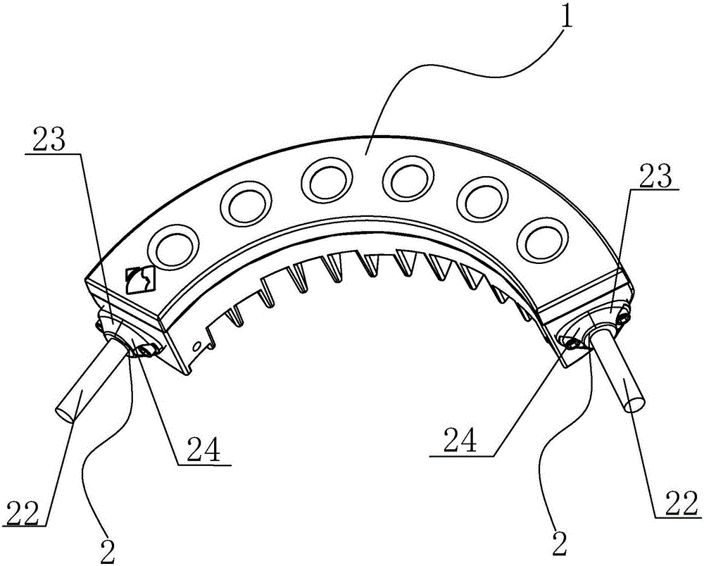
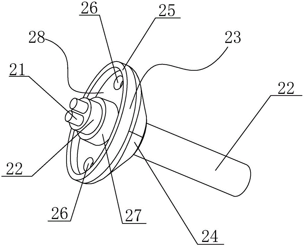
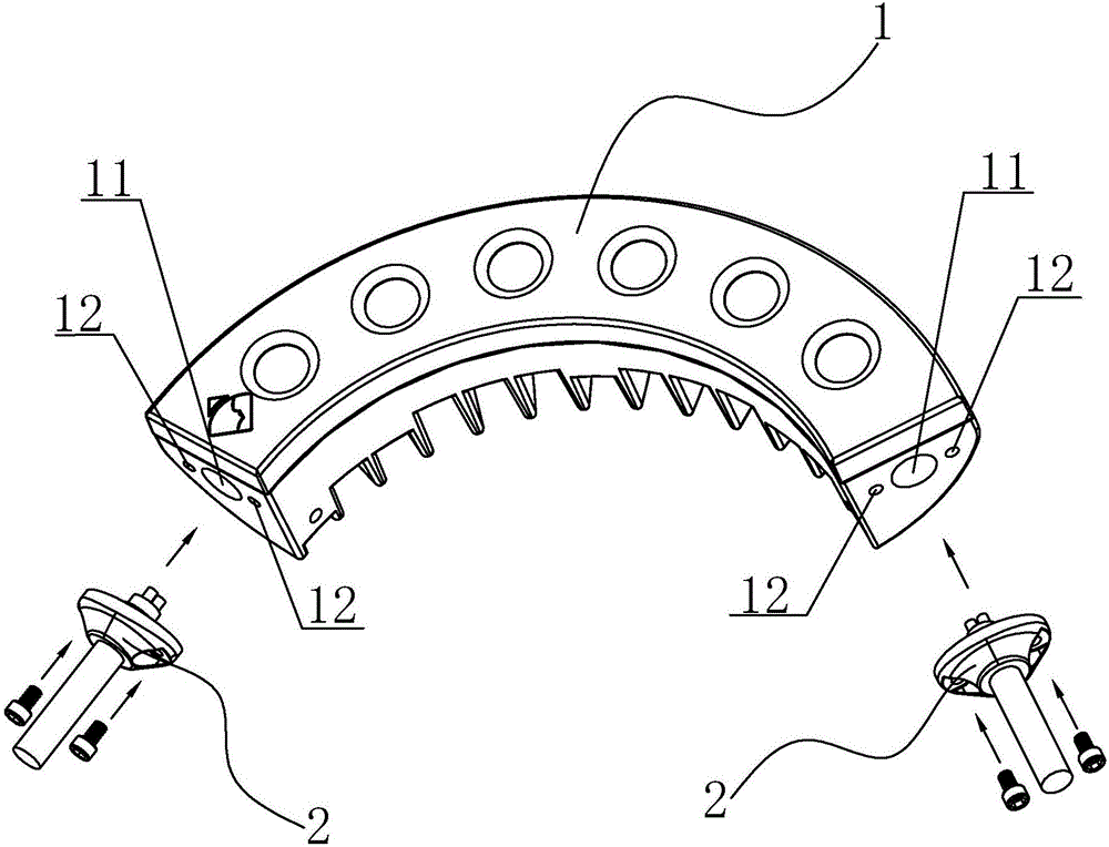
[0015] refer to Figure 1-Figure 3 , an outlet structure applied to a corrugated lamp according to the present invention, comprising a corrugated lamp main body 1 and a waterproof power cord 2, there is a wiring hole 11 on the left and right sides of the corrugated lamp main body 1, and the waterproof power cord 2 passes through the wiring hole 11 Connected to the interior of the main body 1 of the corrugated light, the waterproof power cord 2 includes an electric wire 21, a protective layer 22 for wrapping the electric wire 21 and a plug 23 arranged on the protective layer 22 for blocking the wiring hole 11, and the waterproof power cord 2 is integrated Forming, wherein, the plug 23 includes a slope 24, a bottom surface 25 for covering the wiring hole 11 and a plugging layer 27 for plugging the wiring hole 11. The plugging layer 27 protrudes from the bottom surface 25, and the plugging layer 27 and the wiring hole 11 are matched with each other, the edge of the wiring hole 11...


PUM


Abstract

The invention discloses a wire outlet structure applied to a corrugated lamp. The wire outlet structure comprises a corrugated lamp body and a waterproof power line. The left side and the right side of the corrugated lamp body are provided with wiring hole positions correspondingly. The waterproof power line is connected into the corrugated lamp body through the wiring hole positions. The waterproof power line comprises a wire, a protective layer used for wrapping the wire, and plugs which are arranged on the protective layer and used for plugging the wiring hole positions. The wire cannot be seen from the front face of the corrugated lamp, and thus the appearance of the installed corrugated lamp is attractive. The plugs tightly press the corresponding wiring hole positions, and therefore no water seepage gaps exist, the condition of water seepage caused by plug looseness after long-time use can be avoided, and the good waterproof effect of the corrugated lamp is guaranteed.

Description

technical field [0001] The invention relates to a wire outlet structure applied to corrugated lamps, especially suitable for corrugated lamps requiring combination of waterproof and aesthetic appearance. Background technique [0002] There are generally two types of outlet structures for existing corrugated lights. The first is to lead out the wires from the back of the corrugated lamp, and then install a wire fixer at the outlet to fix the wires. When using this outlet structure, the wires must be wound to the corrugated lamp. The side of the lamp, and then pull it to the ground to connect to the mains. The wires that wind out will make the installation of the corrugated lamp unsightly, and because the outlet is perpendicular to the lamp housing, the waterproof performance is not good; the second is in the corrugated lamp. The wires are led out from the left and right sides, and then waterproof wire fixers are installed at the outlets. This outlet structure can make the ins...

Claims


Application Information

Patent Timeline
Patent Type & Authority Applications(China)
IPC IPC(8): F21S8/00F21V27/00F21V31/00F21W131/10
CPCF21S8/00F21V27/00F21V31/00F21W2131/10
Inventor 曾卓飚
Owner 广东人和照明实业有限公司
Why Eureka
Try Eureka