Pedal device for drum

A pedal and beater technology, which is applied to instruments, percussion instruments, musical instruments, etc., can solve problems such as the inability to drive the pedal smoothly and the decline of pedal operability.

Active Publication Date: 2016-12-07
HOSHINO GAKKI COMPANY LIMITED
View PDF7 Cites 4 Cited by
  • Summary
  • Abstract
  • Description
  • Claims
  • Application Information

AI Technical Summary

Problems solved by technology

In this way, when the friction force between the tension coil spring 101 and the bolt 102 increases, the pedal cannot be driven smoothly, and the operability of the pedal further deteriorates.

Method used


Image

  • Pedal device for drum
  • Pedal device for drum
  • Pedal device for drum

Examples


Embodiment Construction

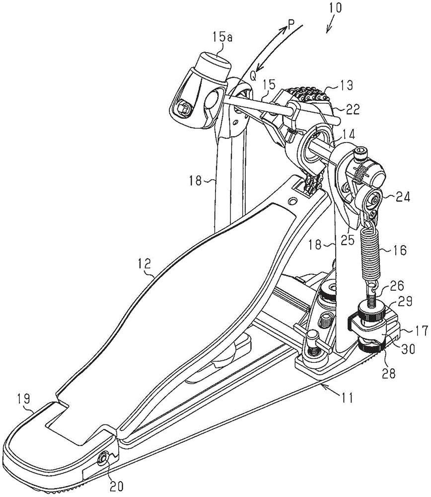
[0020] Refer below Figure 1 ~ Figure 7B An embodiment in which the drum pedal device of the present invention is embodied will be described.

[0021] Such as figure 1 As shown, the drum pedal 10 includes an apparatus main body 11 , a pedal 12 , a chain belt 13 as a transmission member, a shaft 14 , a beater 15 , and a tension coil spring 16 . The device main body 11 is composed of a base 17 and a pair of pillars 18 extending upward from the front end of the base 17 . The pair of struts 18 is arranged with a space between the two struts 18 . A heel portion 19 is attached to the rear end of the base 17 . The rear end of the pedal 12 is rotatably mounted to the heel portion 19 via a support shaft 20 . The front end of the pedal 12 is arranged between a pair of struts 18 .

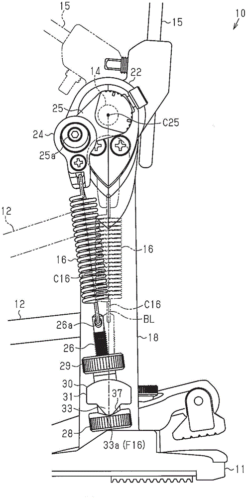
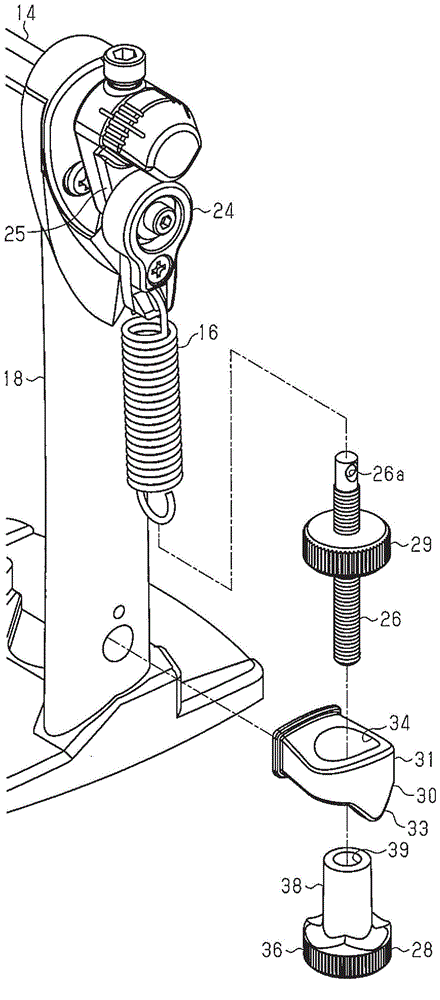
[0022] The shaft 14 is rotatably supported to the upper ends of a pair of struts 18 . A beater 15 and a roller 22 are attached substantially at the center of the shaft 14 . One end of the chain belt 1...


PUM


Abstract

A drum pedal (10) includes a unit body (11), a pedal (12), a chain belt, a shaft (14), a beater (15), and a tension coil spring (16). The tension coil spring (16) has a lower end coupled through a bolt (26), an adjusting nut (28), and a locking nut (29) to a bracket (30) fixed to a column (18). The tension coil spring (16) pivots together with the bolt (26) and the adjusting and locking nuts (28,29) relative to the bracket (30). A pivot fulcrum (F16) of the tension coil spring (16) is provided on the lower surface of the bracket (30) contacting the adjusting nut (28).

Description

technical field [0001] The present invention relates to a pedal device for playing drums such as bass drums. Background technique [0002] As described in Japanese Patent Application Laid-Open No. 2007-017805, a pedal device has been proposed, which includes a base plate, a pedal, a chain, a rotating shaft, a beater, and a tension coil spring. A pair of struts extend upward from the front end of the base plate. A rotary shaft is rotatably supported to the upper ends of the pair of struts. A beater and a roller are installed at the center of the rotating shaft. The pedal is rotatably mounted on the rear end of the floor. One end of the chain is connected to the rotating shaft in a state wound around the roller. The other end of the chain is connected to the free end of the pedal. The upper end of the tension coil spring is connected to a cam attached to the end of the rotating shaft via a connecting rod. The lower end of the tension coil spring is connected to the upper...

Claims


Application Information

Patent Timeline
Patent Type & Authority Applications(China)
IPC IPC(8): G10D13/00G10D13/02
CPCG10D13/11
Inventor 平泽谕
Owner HOSHINO GAKKI COMPANY LIMITED
Why Eureka
Try Eureka