
Rotor component of magnetic levitation motor and its online counterweight method

A motor rotor and magnetic levitation technology, applied in electrical components, electric components, centering/balancing rotors, etc., can solve the problems of difficult operation, unsatisfactory dynamic balance, affecting the service life of the motor, etc., to reduce hardware costs, Conducive to safe and stable operation

Active Publication Date: 2019-02-19
NANJING CIGU TECH CORP LTD
View PDF6 Cites 0 Cited by
  • Summary
  • Abstract
  • Description
  • Claims
  • Application Information

AI Technical Summary

Problems solved by technology

When the requirements for dynamic balancing of the rotor are high, it is relatively difficult to operate on a low-speed dynamic balancing machine
Moreover, even if the dynamic balance is successfully completed on the dynamic balancing machine, when the motor runs at a high speed, its dynamic balance may still not reach the ideal situation, seriously affecting the service life of the motor

Method used


Image

  • Rotor component of magnetic levitation motor and its online counterweight method
  • Rotor component of magnetic levitation motor and its online counterweight method
  • Rotor component of magnetic levitation motor and its online counterweight method

Examples


Embodiment Construction

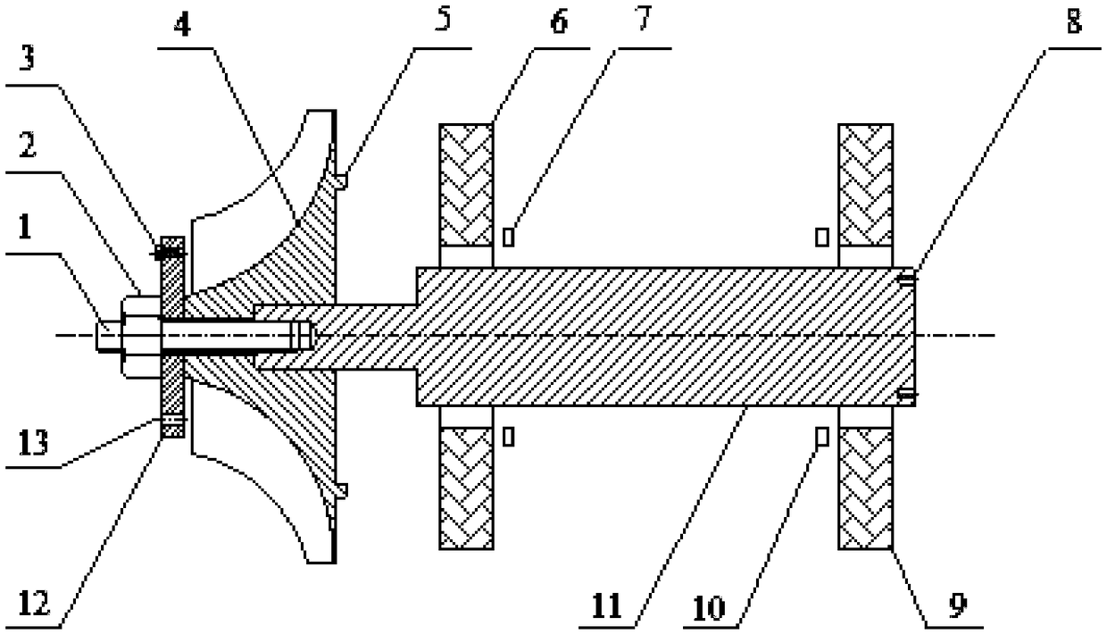
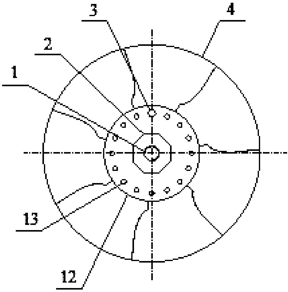
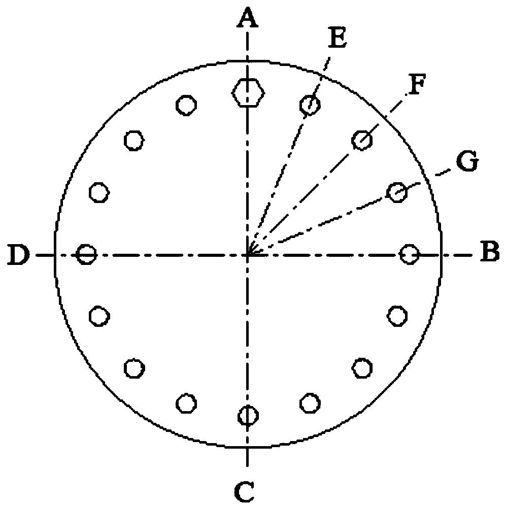
[0024] Please refer to figure 1 and figure 2 As shown, the magnetic levitation motor rotor part of the present invention includes a bolt tie rod 1, a compression nut 2, a weight screw 3, an impeller 4, a first magnetic bearing 6, a first displacement sensor 7, a second magnetic bearing 9, and a second displacement sensor 10. Motor rotor 11, auxiliary counterweight plate 12, the bolt tie rod 1 is fixedly connected to the left side of the motor rotor 11, the impeller 4 is sleeved on the motor rotor 11, and the compression nut 2 is threaded on the bolt tie rod 1 to The impeller 4 is fastened on the motor rotor 11, the auxiliary weight plate 12 is arranged between the compression nut 2 and the impeller 4, the first magnetic bearing 6, the first displacement sensor 7, the second displacement sensor 10 and the second magnetic bearing 9 Sleeve on the motor rotor 11 from left to right in turn.

[0025] Wherein the auxiliary weight plate 12 is installed between the impeller 4 and th...


PUM


Abstract

The invention provides a magnetic levitation motor rotor part and an online weighing method therefor. The magnetic levitation motor rotor part comprises a bolt pull rod, a gland nut, weighing screws, an impeller, a first magnetic bearing, a first displacement sensor, a second magnetic bearing, a second displacement sensor, a motor rotor, and an auxiliary weighing plate, wherein the bolt pull rod is fixedly connected on the left side of the motor rotor; the impeller is arranged on the motor rotor in a sleeving manner; the gland nut is in threaded connection with the bolt pull rod; the auxiliary weighing plate is arranged between the gland nut and the impeller; the first magnetic bearing, the first displacement sensor, the second displacement sensor and the second magnetic bearing are arranged on the motor rotor from left to right in sequence; the auxiliary weighing plate is arranged between the impeller and the gland nut, and multiple weighing screw holes are uniformly formed in the circumferential direction of the auxiliary weighing plate; and the weighing screws are in threaded connection with the corresponding weighing screw holes. By adoption of the magnetic levitation motor rotor part and the online weighing method therefor, the vibration of the motor rotor is reduced to an ideal condition in high-speed operation, so that the safe and stable operation of the magnetic levitation motor can be facilitated.

Description

Technical field: [0001] The invention relates to a magnetic levitation motor rotor component and an online counterweight method thereof, belonging to the technical field of magnetic levitation motors. Background technique: [0002] In the motor industry, the rotor components of the motor need to be dynamically balanced to reduce the vibration of the rotor during operation and improve the life of the motor. The dynamic balance of the rotor is often operated on a dynamic balancing machine, and the dynamic balance speed is generally about 0.3 to 5,000 rpm. Since the working speed of ordinary motors is close to the speed of dynamic balance, the vibration of the rotor after dynamic balance generally meets the requirements when it is working. [0003] In recent years, with the development of high-speed motors, especially the new generation of high-speed motors—maglev motors, higher requirements have been placed on the dynamic balance of the motor rotor. The speed of the high-spe...

Claims


Application Information

Patent Timeline
Patent Type & Authority Patents(China)
IPC IPC(8): H02K7/09H02K15/16
CPCH02K7/09H02K15/165
Inventor 包金哲吴立华董继勇
Owner NANJING CIGU TECH CORP LTD
Learn More