Tooth head structure of stone crusher

A stone crusher and tooth head technology, which is applied in the field of ore machinery and equipment, can solve problems such as unreasonable structural design, affecting work efficiency, and easy damage to the machine tooth structure, so as to achieve good structure firmness of the tooth head, convenient use and installation, and improved The effect of work efficiency

Inactive Publication Date: 2016-12-14
ZHEJIANG PACIFIC MACHINERY CO LTD
View PDF8 Cites 2 Cited by
  • Summary
  • Abstract
  • Description
  • Claims
  • Application Information

AI Technical Summary

Problems solved by technology

After the teeth of the existing mining rock crusher are connected with the drive pivot, they collide with the ore during work, thereby crushing the ore; but the teeth of the existing rock crusher are made of hard metal materials. As a result, under the impact and vibration of ore, the machine tooth structure is easily damaged. Even if the working head of the machine tooth is made of cemented carbide, but the structure design is not reasonable enough, it is easy to cause other parts of the machine tooth to be damaged by ore. Impact, so that the entire machine tooth structure is damaged, and the machine teeth need to be replaced frequently, which affects work efficiency and increases the cost of use

Method used


Image

  • Tooth head structure of stone crusher
  • Tooth head structure of stone crusher
  • Tooth head structure of stone crusher

Examples


Embodiment Construction

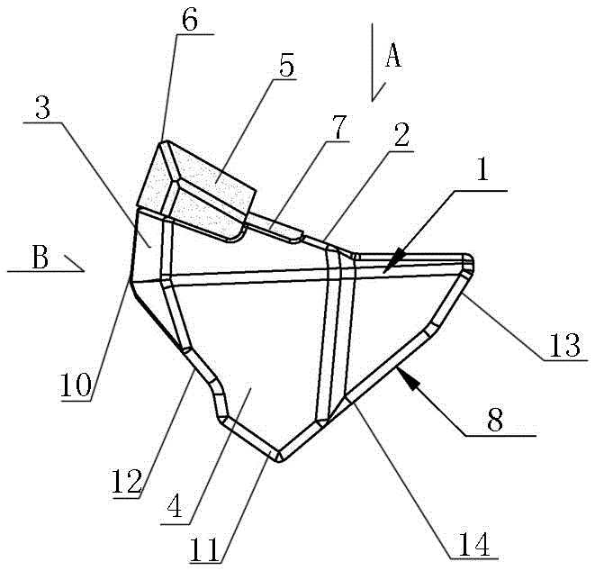
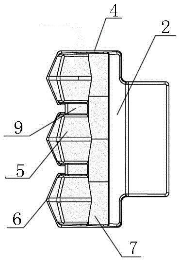
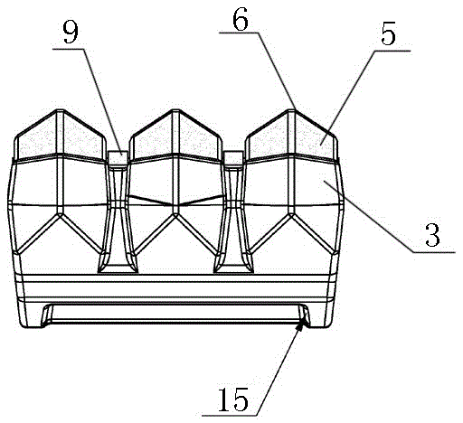
[0010] The present invention will be described in detail below in conjunction with accompanying drawing: Figure 1-3 As shown, the tooth head structure of a rock crusher according to the present invention includes a block-shaped tooth head body 1 that looks like an equilateral triangle when viewed from one side. The upper surface of the tooth head body 1 is a working surface 2, and the working surface 2 A pointed tooth head 3 is provided at the front end, and the two sides of the tooth head body 1 are respectively provided with integral outer bumps that are bounded downwards from the upper working surface 2 and are larger than half of the end surface area 4. The front end of the working surface 2 on the outer convex block 4 is a tooth head 3, which is mainly formed by connecting three large hard alloy blocks 5 arranged in the front row, and each large block The front end portions of the hard alloy blocks 5 are respectively upturned pointed end faces 6, and the teeth head porti...


PUM


Abstract

The invention discloses a tooth head structure of a stone crusher. The tooth head structure comprises a block-shaped tooth head body in the shape like a regular triangle from the lateral view. The upper face of the tooth head body is a work face. The front end portion of the work face is provided with a sharp-angle-shaped tooth head part. Outer protruding blocks are arranged on the two side faces of the tooth head body correspondingly, wherein the outer protruding blocks are integrated, the upper face work face serves as the boundary in a downward manner, and the area of the outer protruding blocks is larger than that of half of an end face. The tooth head part is arranged at the front end portion of the upper face work face of the outer protruding blocks. The tooth head part is mainly formed by connecting three large-block-shaped hard alloy blocks in parallel, wherein the three large-block-shaped hard alloy blocks are arranged in the front row. The front end portion of each large-block-shaped hard alloy is provided with an upwards-tilted sharp-angle-shaped end face. The upper face of the tooth head part composed of the large-block-shaped hard alloy blocks is higher than the work face. A whole-strip-shaped hard alloy block which is transversely arranged and is located on the same horizontal plane with the work face is further inlaid in the position, on the inner sides of the large-block-shaped hard alloy blocks, on the work face. The tooth head structure of the stone crusher has the beneficial effects of being reasonable in structure, convenient to use and install, good in overall tooth head structure firmness, high in wear resistance, capable of improving the work efficiency and the like.

Description

technical field [0001] The invention relates to a tooth head structure of a rock crusher, belonging to the technical field of ore machinery equipment. Background technique [0002] Mining stone crusher is a common mining powder equipment, usually used for primary crushing of ore. After the teeth of the existing mining rock crusher are connected with the drive pivot, they collide with the ore during work, thereby crushing the ore; but the teeth of the existing rock crusher are made of hard metal materials. As a result, under the impact and vibration of ore, the machine tooth structure is easily damaged. Even if the working head of the machine tooth is made of cemented carbide, but the structure design is not reasonable enough, it is easy to cause other parts of the machine tooth to be damaged by ore. The impact will damage the entire machine tooth structure, and the machine teeth need to be replaced frequently, which will affect the work efficiency and increase the cost of u...

Claims


Application Information

Patent Timeline
Patent Type & Authority Applications(China)
IPC IPC(8): B02C13/28
CPCB02C13/28B02C2210/02
Inventor 周志建
Owner ZHEJIANG PACIFIC MACHINERY CO LTD
Why Eureka
Try Eureka