Crusher tooth head of stone crusher

A stone crusher and tooth head technology, which is applied in the field of ore machinery and equipment, can solve problems such as affecting work efficiency, damage to machine tooth structure, and easy damage to machine tooth structure, so as to achieve convenient use and installation, reduce use cost, and improve work efficiency Effect

Active Publication Date: 2016-12-14
ZHEJIANG PACIFIC MACHINERY CO LTD
View PDF7 Cites 4 Cited by
  • Summary
  • Abstract
  • Description
  • Claims
  • Application Information

AI Technical Summary

Problems solved by technology

After the teeth of the existing mining rock crusher are connected with the drive pivot, they collide with the ore during work, thereby crushing the ore; but the teeth of the existing rock crusher are made of hard metal materials. As a result, under the impact and vibration of ore, the machine tooth structure is easily damaged. Even if the working head of the machine tooth is made of cemented carbide, but the structure design is not reasonable enough, it is easy to cause other parts of the machine tooth to be damaged by ore. Impact, so that the entire machine tooth structure is damaged, and the machine teeth need to be replaced frequently, which affects work efficiency and increases the cost of use

Method used


Image

  • Crusher tooth head of stone crusher
  • Crusher tooth head of stone crusher
  • Crusher tooth head of stone crusher

Examples


Embodiment Construction

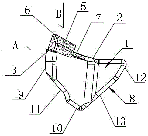
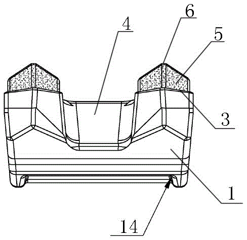
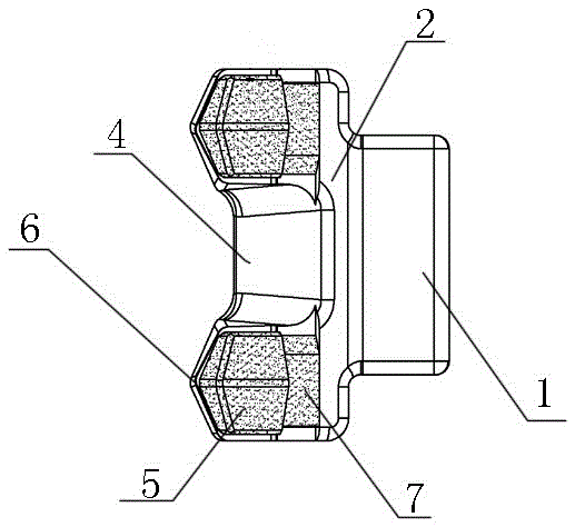
[0010] The present invention will be described in detail below in conjunction with accompanying drawing: Figure 1-3 As shown, a machine tooth head of a rock crusher according to the present invention includes a block-shaped tooth head body 1 that looks like an equilateral triangle when viewed from one side, and the upper surface of the tooth head body 1 is a working surface 2. The surface 2 is located at the front end and is provided with a pointed tooth head 3, and the two sides of the tooth head body 1 are respectively provided with an integrated outer bump 3 that is bounded downward from the upper working surface 2 and is larger than half of the area. The front end of the working surface 2 on the outer convex block 3 is a tooth head 3, and the middle of the tooth head 3 is arranged obliquely downward from the middle position of the working surface with a width greater than one-third of the entire width of the tooth head 3. The inclined-plane notch groove 4, and the tooth h...


PUM


Abstract

A crusher tooth head of a stone crusher comprises a blocky tooth head body with the side-looking shape being similar to a regular triangle. The upper surface of the tooth head body is a working surface, and sharp-corner type tooth head parts are arranged at the front end of the working surface. Integrated outwards-protruding blocks are arranged on the two side faces of the tooth head body correspondingly, the working surface on the upper side downwards divides the outwards-protruding blocks, and the area of the outwards-protruding blocks is larger than half of the area of the working surface. The tooth head parts are arranged at the front ends of upper working surfaces of the outwards-protruding blocks. An oblique-plane notch groove with the width larger than one third of the whole width of each tooth head part is obliquely downwards formed in the middle of the tooth head part from the middle position of the corresponding working surface. Two large blocky hard alloy blocks are arranged on the portions, located on the two sides of the oblique-plane notch groove, of each tooth head part correspondingly. The sharp-tip end face tilting upwards is arranged at the front end of each large blocky hard alloy block. Each tooth head part composed of the large blocky hard alloy blocks is higher than the corresponding working surface. A small blocky hard alloy block located on the same horizontal plane with each working surface is embedded into the portion, located on the inner side of the corresponding large blocky hard alloy block, of the corresponding working surface. The crusher tooth head of the stone crusher has the characteristics that the structure is reasonable, using and mounting are convenient, the whole tooth head is good in structural firmness and resistant to abrasion, and thus the using cost is lowered, and work efficiency is improved.

Description

technical field [0001] The invention relates to a tooth head of a rock crusher, belonging to the technical field of ore machinery equipment. Background technique [0002] Mining stone crusher is a common mining powder equipment, usually used for primary crushing of ore. After the teeth of the existing mining rock crusher are connected with the drive pivot, they collide with the ore during work, thereby crushing the ore; but the teeth of the existing rock crusher are made of hard metal materials. As a result, under the impact and vibration of ore, the machine tooth structure is easily damaged. Even if the working head of the machine tooth is made of cemented carbide, but the structure design is not reasonable enough, it is easy to cause other parts of the machine tooth to be damaged by ore. The impact will damage the entire machine tooth structure, and the machine teeth need to be replaced frequently, which will affect the work efficiency and increase the cost of use. Cont...

Claims


Application Information

Patent Timeline
Patent Type & Authority Applications(China)
IPC IPC(8): B02C13/28
CPCB02C13/28
Inventor 周志建
Owner ZHEJIANG PACIFIC MACHINERY CO LTD
Why Eureka
Try Eureka